Contents
Do all electronic switches respond instantly? Think again. A common misconception among beginners is that an SCR (Silicon Controlled Rectifier) switches on and off immediately. But in reality, timing is everything. In this article on the Tech4Ultra Electrical website, we’ll break down the SCR turn-on time, SCR turn-off time, and the overall Switching characteristics of SCR. By the end, you’ll understand how these dynamic behaviors directly impact circuit performance—especially in power control applications. If you’re aiming to design smarter, more reliable circuits, this guide is your essential starting point.
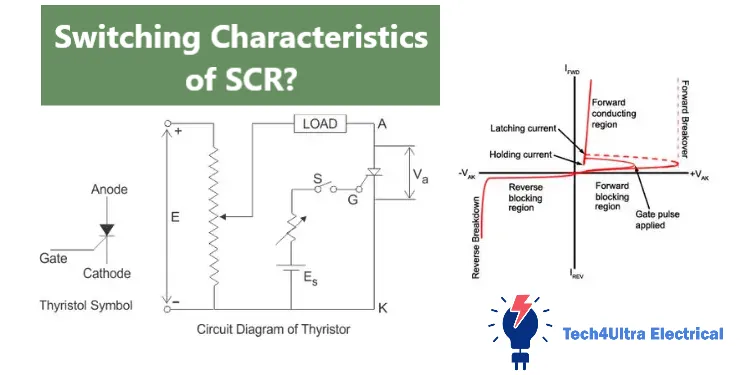
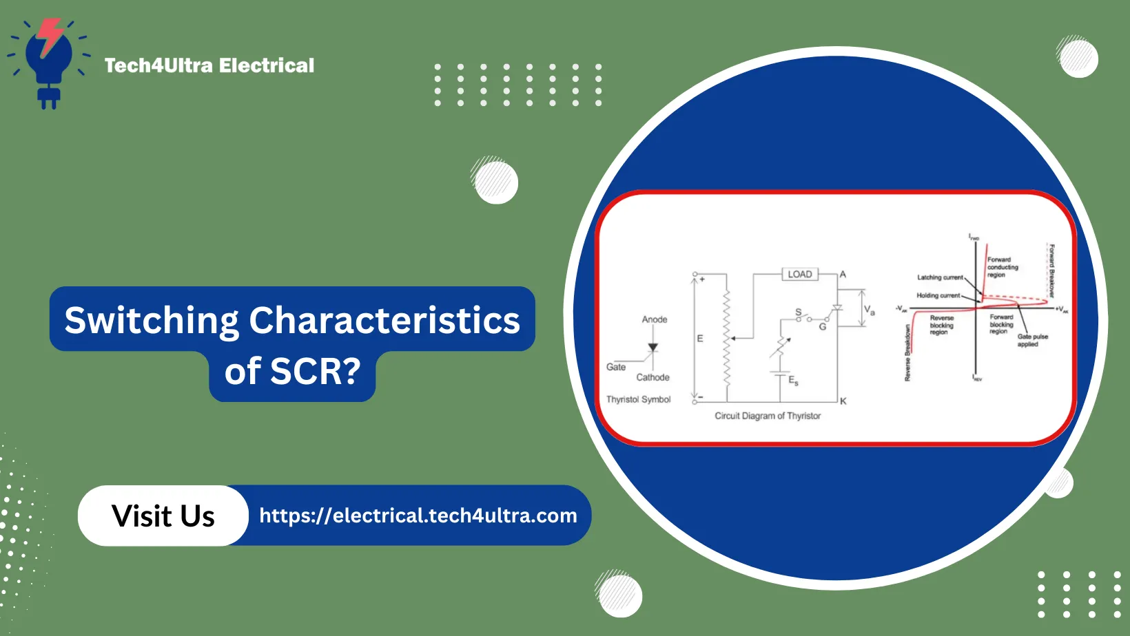
What Happens During Turn-ON in SCRs?
Physical and electrical changes
When I first started working with SCRs, I assumed that applying a gate pulse would make it conduct instantly—flip a switch and it’s on, right? Not exactly. What actually happens is a bit more complex, involving both physical and electrical changes at the semiconductor level.
As soon as the gate receives a sufficient pulse and the anode-to-cathode voltage is forward-biased, current begins to flow. But inside the SCR, there’s a fascinating chain reaction. Electrons and holes start flooding the junctions, especially J2—the middle one. It’s like opening floodgates that were holding back energy. This avalanche effect leads to the regenerative conduction mechanism that characterizes the SCR turn-on time.
Gate triggering and conduction mechanism
The gate current isn’t just a “starter motor”—it’s the actual control handle. Once the gate is triggered, the SCR doesn’t just passively conduct. It actively enters a regenerative feedback loop between its internal layers, making it latch ON even after the gate signal is removed.
I’ve burned a few SCRs back in the day by misunderstanding this. Thinking I could remove the gate pulse too quickly, or worse, applying a weak gate current, led to unpredictable behavior. Lesson learned: always ensure the gate triggering meets the minimum current and pulse duration specified in the datasheet.
Comparison between static and dynamic behavior
Here’s where it gets even more interesting. The static characteristics show a clean forward-blocking to conducting transition on paper. But the dynamic behavior—what really happens during SCR turn-on time—includes delays and voltage drops across junctions, as the internal charge carriers reach equilibrium.
- Static behavior: Idealized and instantaneous.
- Dynamic behavior: Involves finite turn-on delay, voltage overshoots, and time-dependent conduction.
That’s why understanding the Switching characteristics of SCR is key in designing reliable power control systems. It’s not just about turning ON—it’s about turning ON right.
Read Also: Understanding the Schottky Effect: Field Enhanced Thermionic Emission Explained in Depth
SCR Turn-ON Time Components
Delay Time (td)
Back when I first tried timing SCRs in a motor control circuit, I was puzzled by why the current didn’t flow the instant I applied the gate signal. That’s when I discovered the importance of delay time (td).
This is the short time interval between the application of the gate current and the beginning of significant anode current. During this phase, carriers begin to inject into the junctions, but they haven’t saturated enough to support conduction. It’s like revving the engine before the wheels move.
Rise Time (tr)
Once conduction begins, it doesn’t jump from zero to full strength in a snap. That’s where rise time (tr) comes in. It’s the duration over which the anode current ramps up to its final value while the anode-to-cathode voltage drops simultaneously.
During this time, the SCR’s internal resistance falls sharply, allowing current to rise rapidly. Any mismatch in circuit parameters here—like a slow gate pulse or high inductance—can cause problems like voltage spikes or incomplete turn-on.
Spread Time (ts)
This one caught me off guard the first time I encountered uneven current distribution. Spread time (ts) is the phase where conduction spreads evenly across the entire SCR junction area. Initially, conduction begins in a small region near the gate and spreads outward.
If the gate current is weak or the temperature is low, this spread is slower, which can lead to localized heating—something you don’t want. I once lost an SCR because I ignored this and ran high currents before the spread completed.
Practical values and diagrams
In practice, the entire SCR turn-on time (td + tr + ts) can range from a few microseconds to a few dozen, depending on the type of SCR and gate triggering conditions. Power SCRs used in high-frequency circuits are faster, while larger ones used in industrial setups may have longer switching times.
- Delay time (td): 0.5 to 5 µs
- Rise time (tr): 1 to 10 µs
- Spread time (ts): 1 to 15 µs
If you look at an oscilloscope trace, you’ll see a sharp drop in voltage as the current rises—a classic signature of SCR switching.
Role of gate current and temperature
Let me tell you, the gate current isn’t something you can treat casually. Higher gate currents lead to faster turn-on because they inject more carriers instantly. But don’t go overboard—you can damage the junction.
As for temperature, warmer junctions tend to respond quicker because carrier mobility is higher. That said, too much heat can cause premature triggering or thermal runaway. It’s all about balance. Always consult the datasheet for optimal gate current and operating temperature range.
Understanding these components gives you control over the Switching characteristics of SCR—and trust me, when you’re working with sensitive loads or timing-critical applications, this control is everything.
Detailed Turn-OFF Behavior of SCRs
From conduction to blocking mode
If turning on an SCR feels like lighting a fire, turning it off is more like putting that fire out during a windstorm. Once the SCR is ON, it latches itself—meaning it won’t turn OFF just because the gate signal is gone. I learned that the hard way during my first inverter project when I assumed a simple gate logic could shut it down. Spoiler: it didn’t.
To transition from conduction to blocking mode, the current through the SCR must drop below the holding current. This typically happens in AC systems at the natural zero crossing of the waveform. But during that brief moment, the internal junctions are still loaded with charge carriers. The SCR turn-off time is the interval needed for these carriers to recombine or exit, restoring the device to its blocking state.
Importance in inverter circuits and AC systems
This behavior is critical in inverter designs and AC phase-control circuits. Why? Because if the SCR turn-off time isn’t completed before the next gate signal or voltage reversal, the SCR might conduct again unintentionally. That leads to shorts, faulty timing, or worse—blown components.
In my case, I once triggered an SCR in an H-bridge inverter too early after commutation. The SCR hadn’t fully turned off, and I ended up with a nasty shoot-through current. Since then, I always factor in a guard time at least 1.5 times the specified turn-off time.
Bottom line? Switching characteristics of SCR don’t end at the ON cycle. The OFF transition is just as critical, especially when designing circuits that rely on precise timing and controlled switching events. Always respect the recombination time—it’s invisible, but absolutely vital.
SCR Turn-OFF Time Components
Reverse Recovery Time (trr)
When I first got into designing AC control systems, I often ran into issues where the SCR refused to block even after the current hit zero. That’s when I came across the concept of reverse recovery time (trr). This is the time it takes for the SCR to get rid of the stored charge carriers in the junctions—especially after the anode current goes negative.
Think of it like draining water from a sponge. Even if you stop pouring water in, it still takes time for that sponge to dry. During trr, the SCR might still conduct in the reverse direction if you’re not careful with circuit timing. It’s the first major portion of the SCR turn-off time.
Gate Recovery Time (tgr)
Another key but often overlooked piece is the gate recovery time (tgr). I once had a design where I tried to reuse the gate pulse too soon after turn-off. Didn’t work. That’s because the gate junction itself needs time to regain its blocking ability.
tgr is the period needed for the gate circuit to return to its non-conductive state. It’s relatively short but crucial—especially in high-frequency switching. A premature trigger during this time can cause misfires or even latch the SCR unintentionally.
Junction recovery process
Internally, the recovery process in an SCR is about clearing out excess minority carriers from the PNPN structure. After conduction stops, the junctions—mainly J2—are still saturated. Without allowing full recovery, you’re essentially running the SCR in an undefined state. Not good for reliability.
Some high-performance SCRs are engineered to accelerate this process using faster recombination paths, but in general, you must design your circuit around the turn-off constraints.
Effect of load and circuit parameters
One time, I had a circuit with a highly inductive load, and I couldn’t figure out why the SCR kept misfiring during shutoff. Turns out, inductance was maintaining current flow longer than expected—delaying the whole turn-off cycle.
Here’s what I learned:
- High inductance: Slows current decay, extending SCR turn-off time.
- Capacitive snubbers: Can help absorb voltage spikes and reduce false retriggering.
- Gate current shaping: A sharper fall in gate current helps improve gate recovery time.
The Switching characteristics of SCR aren’t just about the silicon—they’re shaped by your entire circuit. So if you’re working with variable loads or high-speed cycles, make sure your design respects both trr and tgr. Trust me, taking shortcuts here leads to long nights troubleshooting.
Practical Comparison: Converter-Grade vs Inverter-Grade SCRs
Speed differences
The first time I had to choose between a converter-grade and an inverter-grade SCR, I honestly thought the difference was mostly marketing. Turns out, it’s all about speed. Converter-grade SCRs have longer SCR turn-off time—typically between 50 to 100 microseconds. They’re built for lower switching frequencies, like in rectifiers or slow AC controllers.
In contrast, inverter-grade SCRs are designed to switch off much faster—often below 10 microseconds. That makes them ideal for high-frequency applications, such as DC-to-AC inverters and chopper circuits. Their entire Switching characteristics are optimized for speed, from gate triggering to junction recovery.
Real-world use cases and component selection
Here’s what that means in practice. If you’re building a battery charger or a basic phase-angle controller for lighting, a converter-grade SCR will do just fine. They’re cheaper, more rugged, and usually easier to source.
But try using one in a high-speed inverter and you’ll regret it. I did. The SCRs couldn’t turn off fast enough, and I ended up with thermal issues and waveform distortion. That’s when I learned to always match the component to the job.
- Converter-grade: Best for low-frequency rectifiers, AC voltage controllers.
- Inverter-grade: Necessary for PWM inverters, UPS systems, high-speed DC drives.
Bottom line? Don’t just grab the first SCR that fits your voltage and current specs. Check the datasheet for SCR turn-on time and SCR turn-off time. That detail could be the difference between a smooth-running circuit and a burned-out disaster.
Factors Influencing Turn-ON and Turn-OFF Times
Temperature
I once built an SCR-based heater controller that worked flawlessly—until summer. As the ambient temperature climbed, the SCRs started misbehaving. That’s when I learned that temperature plays a huge role in both SCR turn-on time and SCR turn-off time.
At higher temperatures, charge carriers move faster, which generally reduces turn-on time. But there’s a flip side: high temps also increase leakage current and lower the holding current, which might cause false triggering or incomplete turn-off. Balance is everything—thermal runaway is real.
Anode current
The anode current at the moment of switching heavily influences timing. Higher current levels can help speed up turn-on by flooding the junctions quickly with carriers. But during turn-off, high anode current means more carriers to clear out, which prolongs the SCR turn-off time.
In one project, I saw SCRs fail to block because I tried to shut them off under peak load. Since then, I always account for current flow when planning commutation timing.
Rate of change (di/dt and dv/dt)
di/dt and dv/dt are tricky. A high di/dt during turn-on can cause localized hotspots if conduction hasn’t spread fully—this is a recipe for junction damage. That’s why I always include a series inductor or resistor in high-current circuits to limit di/dt.
As for dv/dt, if the voltage across the SCR changes too fast while it’s supposed to be off, it might trigger unintentionally. That’s where snubber circuits save the day—they keep the Switching characteristics of SCR within safe limits.
Gate triggering quality
Never underestimate the gate. Poor gate triggering—whether too weak, too short, or noisy—leads to erratic turn-on behavior. I once spent hours troubleshooting a flickering SCR only to find a corroded gate resistor. Lesson: use sharp, clean, and well-timed gate pulses. It’s not just a switch—it’s a system.
How to Optimize SCR Switching in Circuits
Design tips for faster switching
If you’ve ever tried building a high-speed switching circuit with SCRs and ended up with noise, overheating, or erratic behavior, welcome to the club. Optimizing the Switching characteristics of SCR starts at the design table.
One golden rule? Keep your triggering clean. Use gate drive circuits that supply the recommended gate current with fast rise time. Also, minimize stray inductance in the layout—this avoids voltage spikes during switching. A compact, tight PCB layout helps more than you’d think.
Snubber circuits
Now let’s talk about snubbers—your SCR’s best friend. These are RC or RCD networks placed across the SCR to limit dv/dt and absorb voltage transients. I remember one circuit where an SCR kept firing randomly. Turns out, I had skipped the snubber. Once added, the false triggering vanished.
Choose snubber values based on your load and supply voltage. A typical RC snubber might use a 100Ω resistor and a 0.1µF capacitor rated at 600V or higher. Make sure the components can handle repetitive high-frequency stress.
Cooling techniques
SCRs aren’t invincible—they heat up, especially when switching frequently. Heat increases the SCR turn-off time and can eventually cause failure. Use heat sinks and, for high-power setups, consider forced air cooling. I also recommend mounting the SCR on a thermally conductive base and applying thermal paste to improve dissipation.
Monitoring junction temperature is smart too. Many modern circuits now include thermal sensors to prevent overheat damage.
Choosing the right SCR type
Finally, don’t use a slow SCR for a fast job. If you’re designing an inverter or chopper, go with an inverter-grade SCR. They have faster SCR turn-on time and SCR turn-off time. For rectifiers and low-speed switching, a converter-grade SCR will do just fine.
Match the SCR’s voltage and current ratings to your application, and always check the datasheet for switching specs. I’ve learned that choosing the right type upfront saves a lot of headaches down the road.
When all these pieces come together—clean triggering, solid snubbing, proper cooling, and the right SCR—you get switching that’s fast, reliable, and built to last.
Watch Also: Filter Bank in Signal Processing: Types, Applications, and Modern Advances Explained
Application Scenarios and Case Studies
Industrial controls
My first exposure to SCRs was in an industrial heater control system. The SCRs managed high current loads with precision, switching power on and off without mechanical wear. In these systems, fast SCR turn-on time isn’t as critical as robustness and thermal stability.
But here’s a catch: inconsistent SCR turn-off time due to overheating once caused a controller to misfire and overheat an entire section. Since then, we’ve implemented better heat sinking and adjusted triggering circuits for more consistent behavior under load.
UPS and inverter systems
In UPS systems, timing is everything. When the grid fails, the SCR must switch in milliseconds to maintain power continuity. That’s where inverter-grade SCRs shine. Their low turn-off time ensures rapid commutation and smooth transitions.
In one case study, upgrading from older converter-grade SCRs to inverter-grade types reduced waveform distortion and allowed us to increase switching frequency, resulting in smaller transformers and overall improved efficiency.
AC motor drives
Using SCRs in AC motor drives requires balancing torque control with clean waveforms. I’ve worked on VFDs (Variable Frequency Drives) where inaccurate Switching characteristics of SCR caused torque ripple and vibration. By tuning gate pulse timing and adding snubbers, we brought the motor back to smooth operation.
Lesson? Good switching is key to good motor behavior.
Grid switching
Grid interface systems, especially in renewable setups, rely on precise SCR switching to manage phase synchronization and load balancing. Delayed SCR turn-on time or residual charge issues during turn-off can throw off the whole grid match.
Here, real-time monitoring of switching performance and thermal conditions helped maintain reliability—even under fluctuating solar input. SCRs are small components, but their performance can stabilize or destabilize entire systems. Never underestimate them.
Conclusion
Understanding the SCR turn-on time and SCR turn-off time is essential for designing reliable and efficient power electronics. From delay time and rise time during activation to reverse recovery and gate recovery during shutdown, each phase impacts circuit performance.
Key factors influencing Switching characteristics of SCR include:
- Temperature
- Gate current quality
- Load type and current levels
- di/dt and dv/dt rates
Before wrapping up your next design, ask yourself:
- Am I using the right grade of SCR?
- Is my gate trigger circuit sharp and reliable?
- Are snubbers and cooling systems properly rated?
- Have I considered switching timing margins in my control logic?
Master these elements, and you’ll not only avoid costly failures—you’ll build circuits that perform like pros designed them.
FAQs
What are the turn on and turn off characteristics of SCR?
The SCR turn-on time includes three stages: delay time (td), rise time (tr), and spread time (ts), during which the SCR transitions from blocking to full conduction. The turn-off time involves reverse recovery and gate recovery phases where the SCR returns to its non-conductive state after current falls below the holding threshold.
What are the characteristics of SCR?
SCRs exhibit unidirectional current control, latching behavior after triggering, and require a gate pulse for turn-on but none for maintaining conduction. Key characteristics include high current and voltage handling, well-defined Switching characteristics of SCR, and strong thermal stability when properly managed.
What are the characteristics of a thyristor?
A thyristor, like an SCR, has three states: forward blocking, forward conducting, and reverse blocking. It remains off until triggered and continues conducting as long as current stays above the holding level. It offers high efficiency, reliability, and controlled switching through gate input and load current dynamics.
How to turn on and turn off SCR?
To turn on an SCR, apply a sufficient gate pulse while the anode is positively biased. For turn-off, the anode current must drop below the holding current—typically achieved during the zero crossing in AC systems or via forced commutation in DC circuits.
3 thoughts on “Understanding the Schottky Effect: Field Enhanced Thermionic Emission Explained in Depth”