Contents
Have you ever wondered how 3D printers, CNC machines, or robotic arms move with such precision? The answer lies in a powerful yet surprisingly simple device: the stepper motor—more specifically, the bipolar stepper motor. In this article on the Tech4Ultra Electrical website, you’ll discover everything you need to know about how stepper motors work, how to control them, and how to choose the right stepper motor driver. Whether you’re a hobbyist or a professional, understanding stepper motor control can elevate your projects to a whole new level of accuracy and performance.
What is a Bipolar Stepper Motor?
A bipolar stepper motor is a type of stepper motor that uses two winding phases to control movement with high precision. Each phase consists of a coil that can be energized in both directions, allowing the motor to produce torque in a smooth and controlled manner. Unlike traditional motors, a stepper motor moves in discrete steps, making it ideal for applications where accurate positioning is critical.
The two winding phases in a bipolar stepper motor work together by alternating current flow, which changes the magnetic polarity. This interaction causes the rotor to align with the changing magnetic field, generating step-by-step rotation. Because both windings are fully utilized, the motor achieves greater torque output compared to other stepper types.
Unlike a unipolar motor, which requires center-tapped coils and simpler stepper motor drivers, the bipolar variant needs more complex stepper motor control but delivers superior performance and efficiency.
Read Also: Electric Generator: How It Works, Types, and Complete Guide to Electromagnetic Induction
Working Principle of Bipolar Stepper Motors
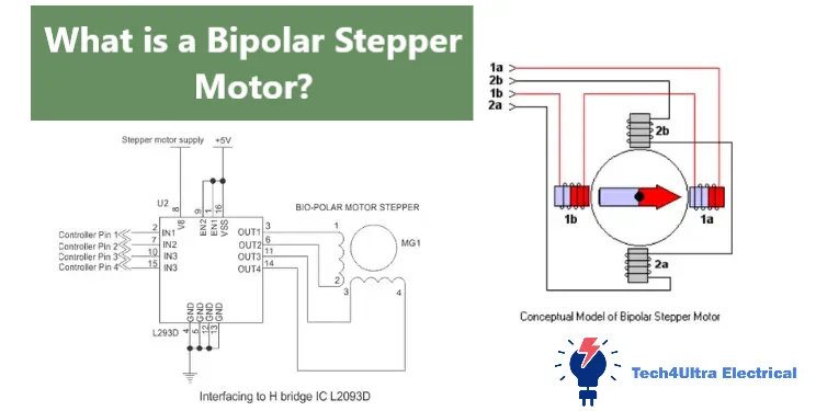
The core operation of a bipolar stepper motor is based on the magnetic interaction between the stator and the rotor. The stator contains two windings (or phases), while the rotor is typically a permanent magnet or a toothed iron core. When current flows through the stator windings, it creates magnetic poles that attract or repel the poles on the rotor. This magnetic force causes the rotor to rotate in precise steps, one increment at a time.
What makes a stepper motor unique is the use of stepper motor control logic to energize the coils in a specific sequence. In a bipolar configuration, alternating current is used to energize the windings in both directions. This is achieved by using an H-bridge stepper motor driver that allows current to reverse, changing the polarity of the magnetic field. This alternating energization results in smooth rotation and higher torque efficiency.
The step sequence for a bipolar stepper motor typically follows a four-step pattern:
- Phase A is energized positively, Phase B is off.
- Phase A is off, Phase B is energized positively.
- Phase A is energized negatively, Phase B is off.
- Phase A is off, Phase B is energized negatively.
This sequence causes the rotor to rotate 90 degrees per cycle. For higher resolution, microstepping techniques can be applied, energizing both phases simultaneously with varying current levels to produce smoother motion.
Diagram (recommended):
Understanding this process is crucial for implementing accurate and efficient stepper motor control in your projects.
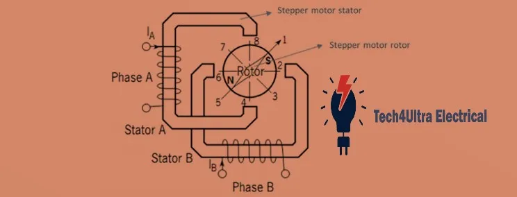
Construction and Internal Components
A bipolar stepper motor consists of a stator and a rotor, both designed to work together to convert electrical pulses into precise mechanical steps. The rotor can be one of two main types: a permanent magnet rotor or a variable reluctance rotor.
The permanent magnet type includes a rotor made of magnetized materials that align with the stator’s magnetic field. It provides higher torque and better step resolution. On the other hand, variable reluctance rotors have soft iron cores without permanent magnetism, and they align with the lowest magnetic reluctance path. These are generally faster but less powerful.
The stator of a stepper motor contains two windings in a bipolar configuration. Each winding is wrapped around pole teeth spaced evenly around the stator. When current flows through these windings, magnetic poles are created that pull the rotor into alignment. Because the windings are energized in alternating directions via a stepper motor driver, the magnetic field rotates step-by-step, driving the rotor forward.
The shaft of the motor is connected to the rotor and transmits the rotation to whatever mechanism the motor is driving. Precision bearings support the shaft, ensuring smooth and stable movement. Around the shaft, the rotor may feature notches or teeth (in the case of hybrid motors) to increase step resolution.
Each coil is carefully wound to handle the motor’s rated current and resist overheating. Efficient stepper motor control depends heavily on the quality and arrangement of these internal components, making the build quality a crucial factor for performance and reliability.
Bipolar Stepper Motor Driver Circuit Explained
Driving a bipolar stepper motor requires precise control of current direction in each winding, which is where the H-Bridge circuit becomes essential. An H-Bridge is an arrangement of four switches (typically transistors or MOSFETs) that allow current to flow in either direction through a coil. Since bipolar motors have two windings, you’ll need two H-Bridges—one for each phase.
Here’s how it works: when switches on opposite corners of the H-Bridge are activated (e.g., top-left and bottom-right), current flows in one direction. Activating the other diagonal (top-right and bottom-left) reverses the current flow. This polarity change is what makes stepper motor control possible in both directions.
For each step, the driver energizes the coils in a specific sequence using the H-Bridges. For instance:
- Step 1: Coil A forward, Coil B off
- Step 2: Coil A off, Coil B forward
- Step 3: Coil A reverse, Coil B off
- Step 4: Coil A off, Coil B reverse
This cycle continues to rotate the rotor. For smoother operation, advanced drivers use microstepping, which energizes both coils simultaneously with different current levels.
Protection and safety are critical in any stepper motor driver design. Common features include:
- Over-current protection to prevent coil burnout.
- Thermal shutdown to avoid overheating.
- Flyback diodes to handle voltage spikes when switching off the inductive loads.
- Current limiting resistors or chopper drivers to manage precise current delivery.
Integrating a driver circuit with a microcontroller like Arduino or STM32 is straightforward. Most modern drivers (like A4988 or DRV8825) have step and direction pins. You send pulse signals from the microcontroller to the STEP pin and control rotation direction via the DIR pin. Libraries like AccelStepper (Arduino) simplify implementation significantly.
This tight integration allows you to write code that moves your stepper motor at custom speeds, accelerations, and directions—enabling everything from 3D printers to robotic arms to operate with surgical precision.
Driving Techniques and Modes
Controlling a bipolar stepper motor involves various driving modes, each offering a balance between torque, precision, and smoothness. The most common methods include full-step, half-step, and microstepping, each managed by a stepper motor driver via PWM and control signals.
Full-step drive is the simplest mode. In this technique, one coil (or both) is energized fully at a time, resulting in a 90° or 45° shift per step depending on the rotor design. It’s robust and produces maximum torque, but movement can be jerky and lacks resolution.
Half-step drive alternates between energizing one and two coils, effectively doubling the number of steps per revolution. This method provides smoother motion and higher resolution than full-step. However, it suffers a slight dip in torque during single-coil steps.
Microstepping takes things further by varying the current through both coils simultaneously using pulse-width modulation (PWM). Instead of binary on/off coil energization, it applies sine and cosine waveforms to generate intermediate positions. This results in extremely smooth rotation, reduced noise, and higher positioning accuracy—perfect for precision tasks like CNC and 3D printing.
The waveform below illustrates microstepping:
Coil A: 100% → 70% → 0% → -70% → -100% ...
Coil B: 0% → 70% → 100% → 70% → 0% ...
These sinusoidal PWM signals ensure that the rotor moves in finer increments, sometimes up to 256 microsteps per full step depending on the driver’s capability.
To implement these modes, the stepper motor control unit (usually a microcontroller) sends timed pulse signals to the driver’s STEP pin. The driver interprets these pulses to sequence the current through the coils accordingly. Directional control is managed via the DIR pin.
Choosing the right drive mode depends on your application—full-step for raw torque, half-step for balanced control, and microstepping for ultra-precise and quiet operation.
Performance Characteristics
One of the key features of a bipolar stepper motor is its ability to maintain position without continuous motion—this is called holding torque. When both windings are energized, the motor resists external forces trying to move the shaft. This is especially useful in applications like CNC machines and 3D printers, where position accuracy is crucial even when the motor is idle.
The relationship between speed and torque is another critical performance factor. A typical stepper motor delivers maximum torque at low speeds. As speed increases, torque gradually decreases due to the motor’s inductance limiting current rise time. This behavior is visualized in the motor’s speed-torque curve, which helps in selecting the right motor for specific loads and response times.
In terms of efficiency, stepper motors are less efficient than DC motors because they continuously draw current, even when holding position. This leads to heat buildup, especially at higher currents or with constant use. Proper stepper motor driver configuration—like enabling idle current reduction or using chopper drive techniques—can help manage this heat.
Effective stepper motor control not only optimizes performance but also extends motor life by reducing unnecessary power dissipation and maintaining stable thermal conditions.
Advantages of Bipolar Stepper Motors
Bipolar stepper motors are widely favored in precision control applications for several compelling reasons. One of their biggest advantages is their ability to deliver higher torque compared to unipolar motors of the same size. This is because both windings are used throughout the step sequence, maximizing magnetic interaction and force output.
Another key benefit is better efficiency. Unlike unipolar motors—which only energize half the coil at any given moment—bipolar designs utilize the full winding, resulting in improved energy usage and greater mechanical output. This makes them ideal for demanding applications like CNC machines, robotics, and automated camera sliders where torque and performance matter most.
While they do require more complex stepper motor driver circuits, especially H-Bridge configurations, the tradeoff is worth it. For developers seeking tighter control and reliable stepper motor control, the bipolar type stands out as a top-tier choice.
Disadvantages and Limitations
Despite their benefits, bipolar stepper motors come with a few trade-offs that need to be considered in system design. The most notable is the complex driver requirement. Because current must reverse direction through each coil, a dual H-Bridge stepper motor driver is necessary. This adds to the design complexity and may increase the cost, especially in multi-axis systems.
Additionally, bipolar motors tend to have higher power consumption. Even when the rotor is not moving, current continues to flow through the coils to maintain holding torque. This constant current draw generates heat, which can become problematic without proper heat dissipation strategies. In mobile or battery-powered applications, this inefficiency may reduce overall system performance.
While stepper motor control techniques like current limiting and idle current reduction can help mitigate these issues, they still require careful configuration to avoid overheating and wasted energy.
Bipolar vs Unipolar Stepper Motor: A Clear Comparison
Choosing between a bipolar stepper motor and a unipolar one depends on your project’s needs—whether it’s raw torque, simplicity, or efficiency. Here’s a side-by-side comparison to help you decide:
| Feature | Bipolar Stepper Motor | Unipolar Stepper Motor |
|---|---|---|
| Wiring Complexity | More complex (4 wires) | Simpler (5 or 6 wires) |
| Driver Requirement | Requires H-Bridge stepper motor driver | Simpler transistor-based drivers |
| Torque Output | Higher torque | Lower torque (only half coil used at a time) |
| Efficiency | More efficient coil usage | Less efficient due to partial coil activation |
| Heat Generation | Higher (due to continuous current) | Lower in general |
| Cost | More expensive overall | Cheaper and easier to implement |
| Applications | CNC machines, robotics, 3D printers | Simple automation, printers, toys |
Bipolar stepper motors are best for performance-critical systems where torque and precision matter. In contrast, unipolar motors are ideal for cost-sensitive applications with basic stepper motor control needs.
Applications of Bipolar Stepper Motors
Bipolar stepper motors are widely used in fields that demand high precision and controlled motion. Their ability to produce accurate steps and hold positions without feedback makes them a preferred choice in various industries.
In CNC machines, they drive linear actuators, spindles, and axis tables with excellent repeatability. The motor’s torque and fine control allow for consistent cuts and engravings, even at varying speeds.
In robotics, these motors power joints, grippers, and wheels, enabling smooth and precise movement. Their ability to hold positions makes them perfect for robotic arms and pick-and-place systems.
3D printers rely on stepper motor control for X, Y, and Z axis movements, as well as extruder feed. Here, microstepping ensures smooth motion and print accuracy, critical for detailed output.
Surveillance systems use bipolar stepper motors in pan-tilt camera mounts for steady and silent positioning. Their quiet operation and fine angular control improve tracking performance.
In the automotive sector, they are used for seat adjustment, mirror control, and headlight alignment systems where repeatable positioning is crucial.
Overall, any system that demands reliable, repeatable, and energy-efficient positioning can benefit from the use of a bipolar stepper motor.
Watch Also: Star Delta Starter: Comprehensive Guide to Working, Circuits, and Applications
Troubleshooting and Common Issues
Even with a reliable setup, bipolar stepper motors can run into common issues that affect performance. Here are the most frequent problems and how to fix them:
Overheating is a common concern, especially when motors are running at high current for extended periods. Stepper motors draw current continuously, even when idle. To manage heat:
- Use a stepper motor driver with current-limiting features.
- Enable idle current reduction if supported.
- Improve ventilation or add heatsinks to dissipate excess heat.
Skipped steps occur when the motor loses synchronization, usually due to rapid acceleration, excessive load, or incorrect microstepping. This leads to loss of position and inaccurate motion. Solutions include:
- Lowering acceleration and speed in the control software.
- Ensuring the power supply can deliver enough current.
- Checking for mechanical obstructions or high resistance in the drivetrain.
Driver misconfiguration is often overlooked. A wrong current setting or incorrect wiring can lead to poor performance or even motor damage. For accurate stepper motor control:
- Double-check coil connections (A+, A-, B+, B-) to avoid incorrect sequencing.
- Use a multimeter to match motor datasheet specs with actual wiring.
- Set the correct current limit using the driver’s potentiometer or firmware.
By identifying these issues early and configuring your system properly, you’ll ensure that your bipolar stepper motor runs smoothly, efficiently, and reliably for any application.
Conclusion
Bipolar stepper motors offer a winning combination of precision, torque, and reliability, making them a go-to solution in modern motion control systems. With proper stepper motor control and the right stepper motor driver, they deliver smooth operation across applications like robotics, 3D printing, CNC machines, and surveillance systems.
Despite the need for more complex circuitry, their benefits in performance far outweigh the limitations. As automation continues to evolve, mastering stepper motor technology remains crucial for engineers and hobbyists aiming to build accurate, dependable, and scalable motion systems.
FAQs
How does a bipolar stepper motor work?
A bipolar stepper motor works by alternating the direction of current in two windings to create a rotating magnetic field. This magnetic field interacts with the rotor’s magnets, causing it to step forward or backward in fixed increments. By energizing the coils in a precise sequence using an H-Bridge stepper motor driver, the rotor moves in accurate, repeatable steps.
How to control a stepper motor?
To control a stepper motor, you need a compatible driver and a controller like an Arduino or STM32. The controller sends pulse signals to the STEP pin on the driver, with another signal to the DIR pin to set direction. Advanced stepper motor control uses PWM for microstepping, offering smoother and quieter motion.
What is a stepper motor and how does it work?
A stepper motor is an electromechanical device that converts digital pulses into mechanical rotation. It operates by energizing stator windings in a defined sequence, creating a rotating magnetic field that moves the rotor step-by-step. This unique design allows for precise position control without the need for feedback systems.
What is the control strategy of stepper motor?
Stepper motor control strategies include full-step, half-step, and microstepping modes. The chosen method determines the smoothness and accuracy of the motor’s movement. Control is achieved by sending timed electrical pulses through the motor driver, which manages current flow through the windings to generate motion.
1 thought on “Electric Generator: How It Works, Types, and Complete Guide to Electromagnetic Induction”