Contents
Have you ever flipped a light switch and nothing happened, even though everything seemed fine? You might have encountered an open circuit or a short circuit—two crucial concepts in understanding any electrical circuit. In this article on the Tech4Ultra Electrical website, I’ll walk you through the key differences between them, using real-world examples and practical insights I’ve learned over time. Whether you’re curious, confused, or just want to avoid common mistakes, this guide will help you grasp these foundational ideas with clarity and confidence.
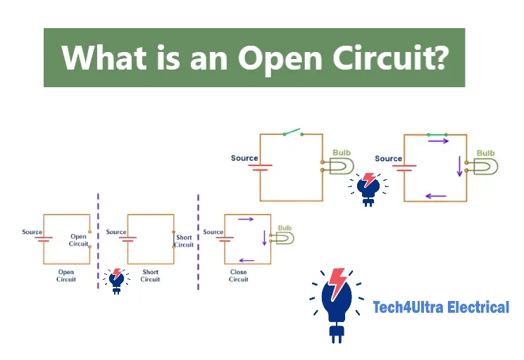
What is an Open Circuit?
Technical Definition
An open circuit occurs when there is a break or interruption in the path of an electrical circuit, preventing current from flowing. Technically, it means the circuit is incomplete—electricity cannot complete its loop from the power source through the load and back again. Think of it like trying to water your garden with a hose that’s cut in the middle; water (or in this case, current) simply won’t flow.
Characteristics: No Current, Voltage Presence
One of the defining traits of an open circuit is the complete absence of current. No electrons are moving because there’s nowhere to go. But—and here’s where many beginners get confused—voltage is still present. You can measure voltage across the open points because the power source still maintains potential. It’s like having a full water tank with the valve shut off—the pressure is there, but no water flows.
Common Causes
Open circuits can happen for a variety of simple reasons:
- A switch turned off (intentionally or accidentally)
- A broken or disconnected wire
- Corroded terminals or loose connections
- A blown fuse or broken component
From experience, I’ve found that a surprising number of open circuit issues come down to something as trivial as a wire coming loose in a terminal block. Always check the basics first!
Read Also: Planar and Non-Planar Graphs Explained with Circuit Examples
Current Flow and Voltage Behavior in Open Circuits
Explanation of Zero Current
In an open circuit, the most important characteristic is that the current is zero. Why? Because there’s no complete path for electrons to move through the electrical circuit. Electricity needs a continuous loop to flow—once the loop is broken, even at a single point, the current stops instantly. No matter how much voltage is applied, current won’t flow without a closed path.
Why Voltage Can Still Exist
Many people assume that if current is zero, there should be no voltage. But that’s not how circuits work. In an open circuit, the voltage from the power source still exists across the open points. Think of it like having pressure in a water pipe while a valve is closed. The pressure (voltage) is there, but the flow (current) is not. The electrical potential difference still exists—it’s just not doing any work.
Formula Breakdown: P = V × I
Let’s break down the power formula: P = V × I, where P is power, V is voltage, and I is current. In an open circuit, I = 0, so the power P becomes zero. That means even if voltage is present, no energy is being transferred or used. This is a key point in understanding circuit behavior.
Resistance in Open Circuits
Ohm’s Law Application
To understand resistance in an open circuit, we need to revisit Ohm’s Law: V = I × R, where V is voltage, I is current, and R is resistance. In an open circuit, the current I is zero. To maintain this equation with zero current and a nonzero voltage, resistance must be extremely high—in fact, theoretically infinite.
Concept of Infinite Resistance
In a practical sense, an open circuit behaves as if it has infinite resistance. There’s no conductive path, so it’s like trying to push water through a completely sealed pipe—nothing gets through. Since resistance resists the flow of current, and there’s no flow at all, we model the resistance as being infinitely large.
Implications for Circuit Analysis
When analyzing an electrical circuit, recognizing an open circuit condition is crucial. It tells you that no current will flow through that branch, which can simplify calculations. Components in that branch may still have voltage across them, but they won’t affect the total current of the circuit. This insight is vital for troubleshooting and designing effective systems.
Open Circuit vs Short Circuit vs Closed Circuit
Comparative Table
| Circuit Type | Resistance | Current | Voltage |
|---|---|---|---|
| Open Circuit | Infinite | Zero | Present |
| Short Circuit | Nearly Zero | Very High | Almost Zero |
| Closed Circuit | Normal Load Resistance | Normal | Distributed Across Components |
Resistance, Current, Voltage Behaviors
Each type of electrical circuit has its own behavior. In an open circuit, resistance is effectively infinite, blocking current completely while voltage can still exist across the gap. A short circuit offers almost no resistance, allowing an uncontrolled surge of current, which is extremely dangerous. A closed circuit has a regular resistance from the load, enabling controlled and intended current flow with proper voltage distribution.
Practical Consequences in Design and Safety
Understanding the differences between these circuits is critical in electrical design and troubleshooting. An open circuit may indicate a fault like a broken wire or failed switch, leading to loss of function. A short circuit can cause severe damage, including fire, due to overheating and high current—hence why safety devices like fuses and breakers are essential. A properly designed closed circuit ensures devices operate efficiently and safely.
As someone who once ignored a loose terminal that caused an open circuit in a lighting system, I can say firsthand: it’s these small details that can make a huge difference in system performance and safety.
Real-World Examples of Open Circuits
Household Example: Switch and Bulb
A classic example of an open circuit can be found in your home—your light switch. When the switch is off, it breaks the electrical circuit, preventing current from reaching the bulb. This is a controlled and intentional open circuit. There’s still voltage across the terminals of the switch, but since the circuit is open, no current flows and the bulb remains off.
Industrial Examples: Machinery and Safety Interlocks
In industrial settings, open circuits are often used as safety measures. Many machines include safety interlock systems that open the circuit when a door is open or a guard is removed. This immediately stops current flow and shuts down the machine, protecting both the equipment and the operator. These are intentional uses of open circuits for safety compliance.
Implications in Troubleshooting
From a technician’s perspective, understanding and identifying an open circuit is crucial in troubleshooting. Symptoms like a motor that won’t start or a light that doesn’t turn on often trace back to a broken wire, loose connection, or faulty switch. I once spent two hours troubleshooting a control panel, only to discover a tiny break in a sensor wire. The voltage was there, but no current flowed. Lesson learned: always suspect an open circuit when devices are unresponsive but the power seems fine.
Watch Also: Sinusoidal Wave Signal: Definition and Examples
Applications and Impacts of Open Circuits
Use in Testing (e.g., Open-Circuit Voltage)
An open circuit is often used deliberately in testing scenarios. One common example is measuring open-circuit voltage, which is the voltage between two points when no load is connected. This test helps verify the health of a power source without drawing current. It’s especially useful in battery testing, where you want to know the voltage before it’s placed under load.
Importance in System Diagnostics
Diagnosing issues in an electrical circuit often starts with checking for open circuits. They’re frequently the reason a device won’t power on. No current means no operation, even if the voltage is technically present. A simple continuity test can quickly reveal where the break is. I’ve used this trick countless times in control panels and circuit boards.
Preventing and Detecting Open Conditions
Preventing open circuits involves ensuring strong, secure connections, especially in terminals, solder joints, and wiring. Regular inspection and maintenance are key. To detect them, technicians often rely on multimeters to test for continuity or voltage drops across components. Early detection can prevent system downtime or costly repairs.
Conclusion
Understanding the behavior of an open circuit is more than just knowing that current stops flowing—it’s about recognizing the role of voltage, resistance, and how they interact within any electrical circuit. Whether you’re designing systems, fixing a household issue, or learning electronics, identifying and managing open circuits is a skill that will always serve you well. As you move forward, remember: a clear grasp of basic circuit types is the first step to mastering electrical safety and performance.
FAQs
What causes open circuits?
An open circuit is caused by a break or disconnection in an electrical circuit. This could be due to a switch being turned off, a broken wire, a blown fuse, or a loose connection.
Can voltage exist in an open circuit?
Yes, voltage can still be present in an open circuit. The power source maintains electrical potential across the open points, even though no current flows.
Is an open circuit safe?
Generally, yes. Since no current flows in an open circuit, there’s no energy transfer. However, if high voltage is involved, the open points could still pose a shock risk.
What is the difference between a short circuit and an open circuit?
An open circuit has infinite resistance and no current flow, while a short circuit has very low resistance and allows excessive current, which can be dangerous.
What is the open circuit?
It’s an electrical circuit that is incomplete, preventing the flow of current, despite the possible presence of voltage.
What is the difference between a short fault and an open fault?
A short fault causes uncontrolled current due to a direct connection, while an open fault stops current entirely because the circuit path is broken.
What is the difference between a short circuit and an open circuit Quizlet?
On Quizlet, the distinction is usually defined as: a short circuit allows excessive current to bypass the load, while an open circuit stops current by breaking the path.
What is the difference between open and short resistors?
An open resistor has infinite resistance and blocks current completely, acting like a break in the electrical circuit. A short resistor, on the other hand, has little to no resistance, allowing full current flow, similar to a short circuit. Both represent faulty or abnormal conditions.
What is the difference between open and short circuit stub?
In transmission line theory, an open stub is a segment of line with an open end (infinite impedance), while a short stub has a grounded end (zero impedance). These stubs are used for impedance matching and signal tuning in RF circuits.
What does short stub mean?
A short stub refers to a piece of transmission line that ends in a short circuit. It reflects signals and can be used to cancel out unwanted frequencies or tune circuits in RF engineering.
What is one difference between open and closed circuit?
An open circuit has a broken path, so no current flows, while a closed circuit is complete, allowing normal current flow through all components.
What is short circuit and open circuit transmission lines?
In transmission lines, a short circuit means the line is terminated with zero impedance, causing maximum reflection. An open circuit means infinite impedance at the end of the line, also causing full signal reflection but with a different phase behavior. Both are used strategically in RF design for controlling signal behavior.
What is open circuit and short circuit test of?
The open circuit and short circuit tests are commonly used for analyzing transformers. The open circuit test measures the core losses and helps determine efficiency, while the short circuit test measures copper losses and helps determine the equivalent impedance and voltage regulation.
Why is it called short circuit current?
It’s called short circuit current because it refers to the high current that flows when the terminals of an electrical circuit are connected with little or no resistance—essentially forming a short circuit. This causes a sudden, often dangerous surge in current.
What is short transmission line?
A short transmission line is a power transmission line typically less than 80 km in length, where the line’s capacitance is negligible and not considered in calculations. Only resistance and inductance are analyzed when evaluating its performance and voltage regulation.
1 thought on “Energy Quanta: The Foundation of Quantum Theory”