
Contents
Have you ever felt overwhelmed by electrical equations and symbols? Whether you’re an engineering student or a tech enthusiast, mastering electrical engineering formulas is your shortcut to solving circuit problems with confidence and speed. In this article on the Tech4Ultra Electrical website, I’ll break down key concepts like the voltage formula, current formula, and more into simple, practical explanations that make electricity feel like second nature.
Brief Overview of the Role of Formulas for Electrical Engineering
I still remember the first time I opened my electrical engineering textbook and stared at what looked like a secret code: V = IR, P = VI, and so on. It felt intimidating at first — but once I understood how these electrical engineering formulas worked, everything changed.
Formulas in electrical engineering aren’t just academic tools. They’re the foundation of every circuit design, power analysis, and troubleshooting task. Whether you’re calculating the voltage formula to design a battery-powered device, or using the current formula to check safe operating conditions, these equations are your go-to compass.
Importance of mastering core equations for exams and fieldwork
If you’re a student, let me be real with you — your exams will throw every possible variation of these formulas at you. I learned (the hard way) that guessing doesn’t cut it. Once I made flashcards for the resistance formula and the electric power formula, my grades took a major leap forward.
But it’s not just about passing tests. In the field, knowing these formulas by heart can literally save equipment, time, and money. When I started my internship, the ability to quickly apply Ohm’s Law impressed my supervisor more than any fancy resume could.
Read Also: Watts Law Explained: Complete Guide to Electrical Power with Examples and Calculations
Fundamentals of Electricity
Voltage, current, resistance definitions
When I first started learning about circuits, the terms voltage, current, and resistance felt abstract — like trying to explain air to someone who’s never breathed. But here’s what made it click for me:
- Voltage (also called potential difference): Think of it as the “push” that moves electric charge through a circuit. It’s what gives energy to electrons so they can flow.
- Current: This is the flow of electric charge. Just like water flowing in a pipe, current is how much electricity is actually moving.
- Resistance: This is what slows the flow down — like friction in a pipe. Every material resists current differently, which is why wire thickness and length matter.
Units and physical interpretation
In practical terms, these quantities are measured as follows:
- Voltage: measured in volts (V)
- Current: measured in amperes (A)
- Resistance: measured in ohms (Ω)
During my first lab session, I connected a resistor and power supply, expecting magic. Instead, nothing happened — until I realized I had used the wrong resistance value. That’s when it hit me: numbers and units aren’t just labels — they define the whole behavior of the system.
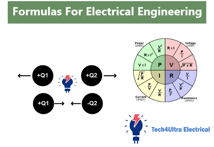
Key formula: V = IR
This is the first electrical engineering formula most of us memorize: V = IR, also known as Ohm’s Law. It tells you that voltage is equal to current times resistance.
I’ve used this voltage formula countless times — to troubleshoot faulty circuits, estimate power requirements, and even impress classmates during lab exams. It’s simple, but don’t underestimate its power. Get this formula right, and you’ve got the key to unlocking every basic circuit analysis problem.
Ohm’s Law and Applications
Formula and vector forms
I used to think Ohm’s Law was just V = IR, but I later discovered it’s deeper than that — especially when you move beyond simple DC circuits.
In its scalar form, it’s straightforward: voltage formula = current × resistance. But when you get into AC circuits, Ohm’s Law takes on a vector (or phasor) form. That’s when voltage and current aren’t just values, they have angles (phases) too.
The vector form looks like this: V⃗ = I⃗ × Z, where Z is the complex impedance — a combination of resistance and reactance. It blew my mind the first time I saw imaginary numbers show up in a circuit equation!
Real-life application in DC and AC circuits
In DC systems — like a car battery or a flashlight — Ohm’s Law helps you find current or resistance instantly. For instance, when I replaced a blown fuse in my old car, I used V = IR to estimate the current the circuit needed to handle.
In AC systems — like home appliances or industrial motors — Ohm’s Law helps with load balancing and power calculations. It’s not just about numbers; it’s about preventing overloads and saving energy costs.
Ohm’s law in resistive, reactive systems
Most people think Ohm’s Law applies only to resistors. I did too — until I worked with capacitors and inductors. In these reactive systems, current and voltage aren’t in sync. That’s where impedance (Z) replaces resistance (R), and suddenly you’re solving with phasors.
Learning to apply Ohm’s Law in both resistive and reactive systems is what made me feel like a real engineer. It’s not hard — it’s just about thinking in terms of time and frequency, not just numbers.
Power and Energy Formulas
Electric power: P = VI, P = I²R, P = V²/R
One of the most satisfying moments in my electrical journey was when I finally understood power — not just the light turning on, but what it actually meant in numbers. The electric power formula gives us three ways to calculate power depending on what data you have:
- P = VI: The classic formula — multiply voltage by current.
- P = I²R: If you only know the current and resistance.
- P = V²/R: If voltage and resistance are given.
I once had to troubleshoot an overheating motor. I thought it was under control until I used P = I²R and realized the current draw was way too high for the wiring. Fixing that saved the motor — and probably my internship.
Energy calculation: E = P × t
Energy is what you actually pay for — in kilowatt-hours. The formula E = P × t is your tool to calculate how much energy a device consumes over time. During a home audit project, I used this to show how much energy old appliances were wasting. It was eye-opening — and convincing for the client!
AC power: real, reactive, apparent power
In AC circuits, power splits into three types:
- Real power (P): Measured in watts (W), this is the usable power.
- Reactive power (Q): Measured in vars (volt-amp reactive), this represents power stored and released by inductors or capacitors.
- Apparent power (S): Measured in VA (volt-amps), this is the combination of both — calculated as S = √(P² + Q²).
Power factor explanation and improvement
Now here’s the sneaky one: power factor. It’s the ratio of real power to apparent power — basically, how efficiently your system is using electricity. A poor power factor means you’re wasting energy.
I worked on a site where the utility charged extra because of a low power factor. We installed power factor correction capacitors — and boom, charges dropped by 20%. That’s the kind of thing clients love.
Resistance and Resistivity
Formula: R = ρℓ/A
During my first soldering project, I couldn’t understand why one wire heated up faster than another — until I learned this formula: R = ρℓ/A. It explains that resistance depends on three things:
- ρ (rho): the material’s resistivity — how much it resists current flow
- ℓ: the length of the conductor — longer wires = more resistance
- A: the cross-sectional area — thinner wires = more resistance
This resistance formula taught me to choose cables not just by price, but by specs. If your wire is too thin or too long, expect voltage drops and heat — which could lead to failure in a real-world setup.
Temperature effects on resistance
Here’s something no one tells you in the beginning: resistance increases with heat — especially in metals. I once noticed dim lights in a circuit under heavy load. Turned out, the wires were overheating, raising resistance, and lowering voltage.
Some materials, like carbon, actually decrease in resistance with heat — but for most conductors, the hotter it gets, the worse it performs.
Materials comparison (copper, aluminum, etc.)
Choosing materials is more than just picking what’s cheap. Copper has lower resistivity than aluminum, meaning it conducts better with less heat loss. But aluminum is lighter and cheaper, so it’s often used in overhead power lines.
In a small home project, I always go for copper — better performance and fewer headaches. But in larger systems, understanding this tradeoff can save both money and energy.
Capacitance and Energy Storage
Capacitance: C = εA/d
Capacitors confused me at first — they didn’t glow, buzz, or move like other components. But once I understood C = εA/d, they started to make sense.
Here’s the breakdown:
- C: capacitance, measured in farads (F)
- ε: permittivity of the material between plates
- A: area of the plates
- d: distance between them
Bigger plates and closer spacing mean more charge storage. I once made a basic capacitor using aluminum foil and plastic wrap just to test this. It worked — barely — but it helped me “feel” what the equation means.
Energy in capacitors: ½CV²
When I built my first LED flasher, I didn’t get why it blinked slowly — until I realized the capacitor was storing more energy than expected. The formula ½CV² tells you how much energy is stored in a charged capacitor.
Double the voltage, and energy goes up four times — something I learned the hard way when a capacitor discharged unexpectedly. Trust me, 12V feels like a tickle… 50V, not so much!
Series and parallel configurations
Capacitors in parallel add up like batteries: more storage. In series, it’s the inverse — total capacitance drops. I made that mistake wiring a timing circuit; put two big capacitors in series, and the timer was way too fast.
Applications in timing circuits
Timing circuits are where capacitors shine. Think camera flashes, blinkers, or even delay-off switches. The charging and discharging curve of a capacitor creates predictable time delays.
In one Arduino project, I used a simple RC timer to delay LED output — no code required. Capacitors may seem passive, but when it comes to time, they call the shots.
Watch Also: Transformer Efficiency Explained: Calculation, Losses, and Optimization Strategies
Inductance and Magnetic Energy
Inductance: L = NΦ/I
When I first dealt with coils, I thought they were just wires wound in circles — until I learned the formula L = NΦ/I. That’s when it hit me: inductance is about how well a coil converts current into magnetic flux.
- L: inductance (henries, H)
- N: number of turns
- Φ: magnetic flux (webers)
- I: current (amperes)
I built a homemade inductor once using copper wire wrapped around a nail. It didn’t perform great, but seeing how turns and current created magnetism was a game changer. More turns = more inductance. Simple, right?
Energy: ½LI²
Just like capacitors store energy in electric fields, inductors store it in magnetic fields. The formula ½LI² tells you how much.
I remember blowing a small transistor when I disconnected a relay coil too fast. That energy had to go somewhere — and it arced through the weakest point. Ever since, I use flyback diodes religiously!
Mutual inductance and coupling coefficient
Mutual inductance is what makes transformers work. It’s the idea that a changing current in one coil induces voltage in another. The key is tight coupling — and that’s where the coupling coefficient (k) comes in.
In a robotics project, I used two closely placed coils to wirelessly transfer power to a moving arm. Not super efficient, but it felt like magic.
AC inductive reactance
In AC circuits, inductors resist changes in current with something called inductive reactance: XL = 2πfL. I used this to filter high-frequency noise in an amplifier project. Want to kill the buzz? Use an inductor — especially at higher frequencies.
But remember: the higher the frequency, the higher the reactance. That’s why audio and RF circuits treat inductors very differently than power supplies.
AC Circuit Analysis Formulas
Reactance: XL, XC
When I started tinkering with audio circuits, one term kept popping up: reactance. It’s like resistance, but frequency-dependent.
- Inductive reactance (XL) = 2πfL: It increases with frequency. The higher the frequency, the more an inductor resists current.
- Capacitive reactance (XC) = 1 / (2πfC): The opposite — it decreases with frequency. Capacitors love high frequencies.
Understanding this helped me filter unwanted noise in a guitar amp build. Knowing whether to block or pass certain frequencies? Reactance is your secret weapon.
Impedance: Z = √(R² + (XL – XC)²)
This formula blew my mind: Z = √(R² + (XL – XC)²). It’s like Ohm’s Law got a makeover for AC. Suddenly, resistance alone wasn’t enough — I had to factor in reactance too.
In one project, I mismatched a speaker’s impedance and it sounded terrible. Once I matched the Z properly using this formula, the clarity was night and day.
Resonance: f = 1 / (2π√LC)
Then came resonance — the frequency where inductive and capacitive reactance cancel each other out. The formula f = 1 / (2π√LC) gave me the sweet spot.
I used this in a metal detector project. At resonance, the circuit was most sensitive — when a metal object passed by, it threw the frequency off. That simple formula made the whole thing work.
Phase angle and power factor correction
When XL ≠ XC, voltage and current go out of sync — that’s the phase angle. The greater the difference, the worse the power factor. Low power factor = wasted energy.
We installed power factor correction capacitors in a workshop to reduce energy bills. Not only did the system run smoother, but it saved real money too.
Time constants: RC and RL circuits
One of my first timer circuits used an RC delay. The time constant τ = RC gave me the exact delay I needed before switching a relay.
In RL circuits, τ = L/R — I learned this building a motor soft-starter. These tiny formulas hide in every real-world delay, ramp-up, and shutoff behavior you see.
Electromagnetic Field Equations
Electric field: E = F/q
Let’s be honest — the first time I saw E = F/q, it felt like high school physics all over again. But in electrical engineering, understanding the electric field is crucial. This formula means that the electric field (E) is the force (F) felt by a charge (q).
During a high-voltage lab experiment, a spark jumped between two metal plates. That’s when I realized — that was the electric field in action, not some mystery spark!
Gauss’s Law, Coulomb’s Law
Gauss’s Law blew my mind. It states that the total electric flux out of a closed surface equals the enclosed charge divided by permittivity. I used it in a simulation to model charge distribution in a capacitor array — and it explained why edge effects happen.
Coulomb’s Law, on the other hand, is more direct: it calculates the force between two charges. It taught me early on why grounding and shielding are essential in sensitive circuit design — stray charges can push or pull unexpectedly.
Magnetic flux: Φ = B·A
When I wrapped a coil around a metal core and waved a magnet nearby, I saw current flicker on a scope. That’s magnetic flux at play: Φ = B·A, where B is the magnetic field strength and A is the area the field passes through.
It’s also why transformers hum. Changing magnetic flux induces current — whether you want it or not.
MMF: F = NI
Magnetomotive force (MMF) was new to me until I built a relay driver. The formula F = NI means more turns or more current = stronger magnetic force. I doubled the coil turns once and immediately got a stronger pull — MMF proved its point!
Maxwell’s law references
Maxwell’s Equations are the ultimate big picture. They connect electricity, magnetism, and even light. I won’t pretend I’ve memorized them all — but knowing how they link changing electric fields to magnetic ones helped me deeply understand how antennas and EM waves work.
It’s like the moment when you realize: this isn’t just math — it’s how the universe works.
Transformers and Electrical Machines
Transformer EMF equation
I still remember the buzz — literally — the first time I powered up a transformer. What drives this core component? The transformer EMF equation: E = 4.44 f N Φ. It tells you the induced EMF is directly proportional to frequency, number of turns, and the peak magnetic flux.
When I wound my own transformer for a school project, I underestimated the number of turns. The voltage came out way too low. That’s when this formula really stuck with me.
Turns ratio, voltage regulation
The turns ratio is what makes transformers magical: Nprimary/Nsecondary = Vprimary/Vsecondary. Want to step down 220V to 12V? It’s all about the ratio.
I used it when wiring a low-voltage lighting circuit — I got the voltage regulation wrong at first, but tweaking the turns gave me a stable output.
Losses: core, copper, hysteresis
Transformers aren’t perfect. I learned that during an energy audit, where some units ran hot. Here’s what causes losses:
- Copper losses: due to resistance in windings — I²R style, just like any conductor.
- Core losses: due to eddy currents in the core metal, especially at high frequency.
- Hysteresis losses: from repeated magnetization — the iron literally resists changing states.
Good design means choosing materials and winding styles to reduce all three.
Induction motor speed and torque formulas
Working with motors taught me this: theory matters when troubleshooting. The synchronous speed is given by Ns = 120f / P. I used this to figure out why a fan ran slow — it was wired for 50 Hz but getting 60 Hz!
As for torque, it’s a bit complex, but this stuck with me: torque drops if you under-volt the motor. The slip and rotor resistance determine how much torque you can pull under load — something I noticed while tuning a conveyor system. The motor was stalling under startup load until I adjusted for correct supply conditions.
In short, transformers and motors aren’t just “plug and play.” These formulas are what make them work — and what help you fix them when they don’t.
DC Machines and Performance Equations
Back EMF
My first real encounter with back EMF was during a bench test of a small DC motor. I connected it to a battery, and it spun — but the voltage across it dropped less than expected. That’s when I learned: as the motor spins, it generates a voltage in the opposite direction — called back EMF.
The formula is simple: Eb = V – I·R, where Eb is the back EMF. It’s nature’s way of limiting runaway current in motors — and it’s also what makes regenerative braking possible in electric vehicles.
Torque generation
Torque in DC machines follows T = kΦIa, where Φ is the magnetic flux and Ia is armature current. I learned this while adjusting a DIY electric go-kart build. Boosting current helped — but the biggest difference came from using stronger magnets to increase flux. More Φ = more torque!
But overdoing it cooked the brushes — lesson learned: torque and temperature are closely related in DC machines.
Efficiency and losses
DC machines aren’t perfectly efficient. You’ve got:
- Copper losses: due to resistance in armature and field windings (I²R again)
- Brush friction losses: physical contact means wear and heat
- Iron losses: from magnetic hysteresis in the core
I once measured a 70% efficient motor under load. The missing 30%? Lost as heat, vibration, and resistance. Improving efficiency often means better materials, tighter tolerances, and smart thermal design.
In the field, these tiny details separate a good motor from a great one — and understanding the formulas helps you diagnose problems before they become failures.
Summary Formula Sheet
Tabulated list of key formulas
If you’re like me, you’ve probably flipped through dozens of pages during last-minute study sessions looking for that one formula. Here’s a compact, categorized formula sheet — the ultimate cheat code for exams and field calculations.
Grouped by category for quick access
| Category | Formula | Description |
|---|---|---|
| Basic Electrical | V = IR | Ohm’s Law – voltage formula |
| P = VI, P = I²R, P = V²/R | Electric power formula | |
| E = P × t | Energy consumption over time | |
| Resistance | R = ρℓ/A | Resistance formula based on material and geometry |
| Capacitance | C = εA/d | Parallel plate capacitor |
| E = ½CV² | Energy stored in a capacitor | |
| Inductance | L = NΦ/I | Inductance of a coil |
| E = ½LI² | Energy stored in an inductor | |
| AC Circuits | Z = √(R² + (XL – XC)²) | Impedance in RLC circuits |
| f = 1 / (2π√LC) | Resonant frequency | |
| Machines | E = 4.44 f N Φ | Transformer EMF equation |
| Ns = 120f / P | Induction motor synchronous speed | |
| DC Machines | Eb = V – I·R | Back EMF |
| T = kΦIa | Torque in a DC motor |
Bookmark this chart or print it out — it’s your quick reference for exams, labs, and real-world troubleshooting!
Watch Also: Rise Time: Definition, Formula, and Practical Examples
Practical Applications and Exam Tips
Common mistakes to avoid
I’ve made plenty of mistakes with electrical engineering formulas, especially early on. The most common? Mixing up units — like using milliamps instead of amps in the current formula, or centimeters instead of meters in R = ρℓ/A. One small slip, and the whole answer is off by a factor of 1000.
Another trap: forgetting which power formula to use. If you’re given current and resistance, don’t use P = VI; go with P = I²R. It’s simple, but easy to overlook in a timed test.
Problem-solving techniques
- List your knowns and unknowns: Write everything down before diving into formulas.
- Check your units: Always convert values to SI units before solving.
- Start with the simplest form: Use Ohm’s Law first, then build from there.
- Estimate before solving: A quick mental check can prevent obvious mistakes.
During my exams, I learned to label diagrams clearly and underline what’s being asked — especially in multi-step questions. That clarity helped me stay focused under pressure.
Real-world formula use cases
I used V = IR to troubleshoot faulty wiring in a client’s smart lighting system. Knowing P = V²/R helped me choose safe resistors for an Arduino project. And in a battery sizing job, E = P × t told me exactly how much energy the system needed daily.
These formulas aren’t just for tests — they’re tools I reach for every day.
Conclusion
If there’s one thing I’ve learned on this journey, it’s this: the more you practice these electrical engineering formulas, the more they become second nature. At first, I struggled to remember which formula applied where — but over time, with enough repetition and real-world problem solving, they stuck.
Don’t be discouraged by complexity. Start small, apply formulas in your daily exercises or hobby projects, and build from there. Whether you’re preparing for an exam or troubleshooting a circuit in the lab, mastering the voltage formula, current formula, and electric power formula will give you a strong foundation to grow from.
So grab your notebook, test yourself regularly, and don’t shy away from mistakes — they’re often the best teachers. Keep at it, and soon enough, you’ll solve problems not just with accuracy, but with confidence.
FAQs
What are the most important electrical engineering formulas?
Start with the fundamentals: V = IR (Ohm’s Law), P = VI (electric power formula), R = ρℓ/A (resistance formula), and E = P × t (energy). For AC circuits, don’t forget Z = √(R² + (XL – XC)²) and f = 1 / (2π√LC). These cover 80% of what you’ll use in both exams and real-world design.
Which formulas are used in power systems?
Power engineers rely heavily on P = VI, P = V²/R, and power factor equations. In transmission and distribution, impedance formulas and transformer EMF equations like E = 4.44 f N Φ are essential. You’ll also need inductive reactance (XL) and apparent power (S = √(P² + Q²)) for load flow analysis.
How to memorize formulas effectively?
For me, writing each formula by hand, then applying it in practice problems, worked best. I used sticky notes, flashcards, and even made diagrams. Try associating each formula with a real-life use case — like P = I²R for heating effects or C = εA/d when designing capacitors. Repetition plus context = long-term memory.
What are the basic electrical formulas?
The core ones are: V = IR (Ohm’s Law), P = VI (power), E = P × t (energy), and R = ρℓ/A (resistance based on material). Master these and you’ll have a solid grip on most electrical problems.
What are all the electricity formulas?
“All” might be a stretch, but the essentials include: voltage, current, resistance, power, energy, capacitance (C = εA/d), inductance (L = NΦ/I), AC impedance, resonance frequency, and motor equations. Most applications build on these.
What is the typical electrical formula?
The most typical — and most used — is V = IR. It appears in almost every electrical calculation, from simple circuits to complex systems. You’ll also see P = VI in just about every design involving power consumption.
What math is most important for electrical engineering?
Get comfortable with algebra, trigonometry, complex numbers, and calculus. For AC circuits, you’ll use phasors and imaginary numbers. In control systems or signal analysis, Laplace and Fourier transforms become essential. Don’t worry — it gets easier with practice and real examples.
2 thoughts on “Watts Law Explained: Complete Guide to Electrical Power with Examples and Calculations”