Contents
Have you ever wondered why some electronic circuits switch states so smoothly and reliably? The answer lies in clever concepts like the Schmitt Trigger, Hysteresis, and the Comparator with hysteresis. In this article on the Tech4Ultra Electrical website, you’ll discover how these simple yet powerful tools reduce noise and enhance stability in analog circuits—giving you the confidence to know when and how to use them in your own designs.
What is a Schmitt Trigger?
Concept and fundamental behavior
I still remember the first time I came across a Schmitt Trigger in a basic electronics course. I couldn’t understand why anyone would need a special kind of comparator. Turns out, the Schmitt Trigger isn’t just a fancy term—it’s a smart way to clean up noisy signals. Unlike a standard comparator, a Schmitt Trigger has built-in hysteresis, meaning it uses two different threshold voltages—one to switch ON, and another to switch OFF. This gap between the thresholds filters out small fluctuations in the input signal, preventing false triggering. It’s perfect for converting analog signals into stable digital outputs, especially when the input is noisy or slowly changing.
Comparator vs. Schmitt trigger
Here’s the deal: both a comparator and a Schmitt Trigger compare input voltages—but only one is noise-resistant. A typical comparator switches output when the input crosses a single threshold. But the Comparator with hysteresis (a.k.a. Schmitt Trigger) adds that “dead zone” between two voltage levels. It’s this hysteresis that helps avoid rapid on-off switching due to small input jitters.
Real-world analogy (e.g., thermostat, switch hysteresis)
Think of a thermostat. It doesn’t turn the heater on at exactly 20°C and off at 20°C—that would make it switch constantly. Instead, it might heat until 22°C and cool down until 18°C. That range is hysteresis. The Schmitt Trigger behaves the same way. It waits until a clear signal crosses a defined high threshold to switch ON, and only turns OFF when the signal dips below a lower threshold. Simple but genius.
Read Also: Understanding Open Circuits: Definition, Behavior, Resistance, and Key Comparisons
The Science Behind Hysteresis
Explanation of hysteresis loop
Let me tell you—understanding hysteresis changed how I viewed analog electronics. Imagine slowly increasing and decreasing an input voltage. With a Schmitt Trigger, the output doesn’t just flip ON and OFF at the same point. Instead, it forms a loop when plotted: that’s the famous hysteresis loop. It’s not just a curve; it’s a visual proof that the system “remembers” where it’s been. That’s why hysteresis is so useful—it keeps circuits from reacting to every tiny glitch or bit of noise.
Voltage threshold concepts: VUT and VLT
Now for the technical meat. A Comparator with hysteresis relies on two threshold voltages: the Upper Threshold Voltage (VUT) and the Lower Threshold Voltage (VLT). When the input rises above VUT, the output switches high. But it won’t switch back low until the input drops below VLT. This gap between VUT and VLT is the heart of hysteresis. It introduces intentional delay, and that’s what filters out unstable transitions.
Memory effect and bistability
Here’s what’s cool: this behavior means the Schmitt Trigger has a form of memory. Depending on whether the signal was last high or low, it remembers and holds its output until it has a good reason to change. That’s called bistability—the ability to hold one of two states reliably. It’s why Schmitt Triggers are often used in digital circuits where a stable ON or OFF state is critical.
Circuit Design Basics
1. Non-Inverting Schmitt Trigger using Op-Amp
One of the first circuits I built in college was a non-inverting Schmitt Trigger using an op-amp. It blew my mind how stable the output became! In this design, the input signal goes directly to the non-inverting terminal of the op-amp. A voltage divider provides positive feedback to the inverting terminal, creating that famous hysteresis.
Formula: The upper threshold (VUT) and lower threshold (VLT) are determined by the resistor ratio: VUT = Vref × (R2 / (R1 + R2)) and VLT = VUT - ΔVh.
2. Inverting Schmitt Trigger using Op-Amp
If you want the output to flip when the input falls instead of rises, try the inverting version. Here, the input connects to the inverting terminal, and the positive feedback goes to the non-inverting side. It’s perfect for sensor signals that drop instead of spike.
Formula: Thresholds depend on the reference voltage and feedback network: VUT = Vref + (R2 / (R1 + R2)) × Vout (when output is HIGH), and VLT = Vref + (R2 / (R1 + R2)) × Vout (when output is LOW).
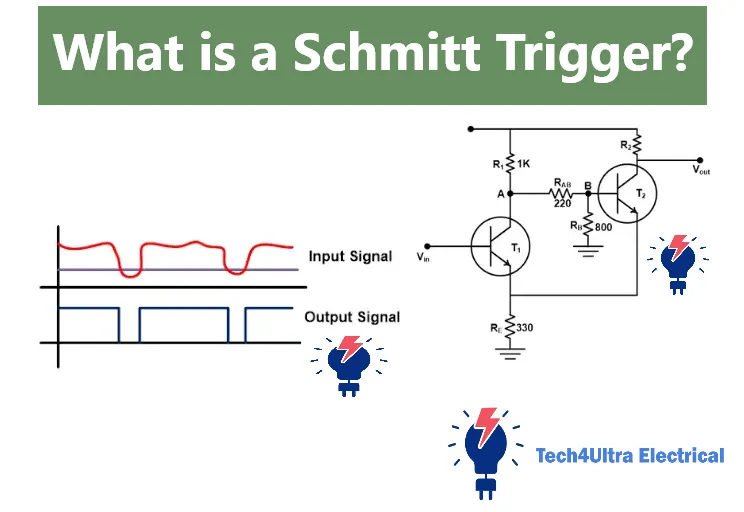
3. Schmitt Trigger using Transistors
Before I had access to op-amps, I experimented with a transistor-based Schmitt Trigger. It’s simpler than it sounds! Two NPN transistors form a regenerative feedback loop. When the input voltage rises, the first transistor turns on, triggering the second, and vice versa when it drops.
This setup naturally creates hysteresis, even if the math is less precise. Still, it’s a great learning experience if you want to understand Comparator with hysteresis logic from the ground up.
4. Schmitt Trigger with Zener Diodes
Want to set fixed voltage thresholds without worrying about resistor values? Zener diodes to the rescue. By using Zeners in the feedback path, you can define exact switching levels—great for power supply monitors or overvoltage detection circuits.
Formula: The thresholds are close to the Zener breakdown voltages, adjusted slightly by series resistor drops. For instance: VUT ≈ Vz1 + Vbe, and VLT ≈ Vz2 + Vbe.
Illustration Tip: Each of these circuits is worth sketching out. Add labels for R1, R2, Vref, Vout, and input to help visualize how feedback and thresholds are formed. It really helps solidify how hysteresis is introduced.
Component Selection and Practical Considerations
Choosing resistors for hysteresis range
Let me tell you, resistor choice can make or break your Schmitt Trigger. I once picked values that were too close, and the hysteresis effect barely kicked in. The key is setting the feedback resistor (R2) and the input resistor (R1) to define the voltage gap you want between switching thresholds. Want a wide hysteresis range? Go for a higher R2/R1 ratio. Want it tight? Keep them closer. But always double-check your math—it saves time and solder.
Power supply issues and rail-to-rail considerations
I learned the hard way that not all op-amps are rail-to-rail. Some won’t hit the full 0V or supply voltage on the output, which messes with your expected threshold voltages. If you’re using a Comparator with hysteresis in a battery-powered circuit, make sure it’s either rail-to-rail or adjust your design accordingly. Also, keep an eye on op-amp output swing specs—they’re not all created equal.
Stability and temperature effects
One summer, my circuit behaved perfectly in the morning and flipped out by noon. Turns out, temperature drift had shifted my voltage thresholds. Thermal effects on resistors and diodes can affect Schmitt Trigger performance, especially if you’re working in an unregulated environment. Use precision resistors and thermally stable components when it counts—your future self will thank you.
Applications of Schmitt Triggers
Switch debouncing
If you’ve ever dealt with physical push buttons, you’ve seen that annoying “bouncing” problem—where a single press registers as multiple signals. That’s where a Schmitt Trigger shines. By adding hysteresis, it filters out the tiny, rapid fluctuations and produces one clean transition. I used it in a home project to stabilize a reset button, and it completely solved the issue—no need for complex software debouncing.
Signal conditioning
Analog sensors often produce noisy or slow-changing outputs. Feeding them directly into a digital input? Not ideal. With a Comparator with hysteresis, I could convert an unstable analog signal into a rock-solid digital one. For example, a temperature sensor with slight fluctuations can trigger false alarms—until a Schmitt Trigger stabilizes its output. It’s like putting a filter between the real world and your logic circuit.
Relaxation oscillator design
Here’s a fun one—using a Schmitt Trigger to build an oscillator. Add a resistor, a capacitor, and let feedback do the rest. I once used this to make a flashing LED for a low-budget timer. As the capacitor charges and discharges through the resistor, the hysteresis ensures clean, periodic toggling. It’s simple and surprisingly reliable.
Waveform shaping (e.g., square wave generation)
Need a square wave from a messy sine signal? Easy. Pass it through a Schmitt Trigger. The dual thresholds clip the signal cleanly, turning wobbly inputs into perfect logic-level square waves. This was super useful when working with an audio signal for a tone decoder project.
Interfacing analog signals with logic inputs
I often use Schmitt Triggers as the “middleman” between analog sensors and digital systems. Most microcontrollers can’t handle analog noise at their inputs. A Comparator with hysteresis solves this by stabilizing transitions before handing them off to the logic domain. It’s practically essential in industrial environments.
Use in microcontrollers and embedded systems
Modern microcontrollers love clean edges. Feeding them jittery analog signals can cause erratic behavior. That’s why Schmitt Triggers are sometimes built right into the GPIO inputs. But when they’re not, I add an external Comparator with hysteresis. It’s saved me in so many real-world embedded projects, especially with sensors and switches.
Common ICs Featuring Schmitt Triggers
Popular ICs (e.g., 555 Timer, 74HC14, LM311)
If you’re diving into Schmitt Trigger circuits, a few integrated circuits (ICs) will keep popping up. The legendary 555 Timer, for instance, is internally built on a Comparator with hysteresis. It uses two threshold voltages to set its trigger and reset points—making it ideal for oscillators and timers. Then there’s the 74HC14, a hex inverting Schmitt Trigger designed specifically for signal conditioning and digital logic shaping. Lastly, the LM311 is a versatile analog comparator that can be configured with external resistors to introduce hysteresis, offering precision in analog-to-digital transitions.
Comparison table: Features, thresholds, use cases
| IC | Type | Hysteresis | Typical Use |
|---|---|---|---|
| 555 Timer | Analog Timer | Internal (~1/3 & 2/3 Vcc) | Oscillators, Pulse Generators |
| 74HC14 | Digital Inverter | Built-in | Signal Debouncing, Logic Input Conditioning |
| LM311 | Comparator | External (via resistors) | Voltage Monitoring, Analog-to-Digital Interfaces |
Simulation and Testing
How to simulate Schmitt trigger in LTspice or Proteus
If you’re like me and prefer to test before soldering, simulation is your best friend. Tools like LTspice and Proteus make it easy to model a Schmitt Trigger circuit and tweak values on the fly. In LTspice, I usually start with an op-amp, two resistors for the feedback network, and a voltage source as input. Just run a transient analysis with a slow ramp input, and you’ll see the hysteresis in action—output flipping at two different voltages. In Proteus, you can simulate it visually with scope probes and animated components, which is great for presentations or beginners.
Real-world scope traces of input vs. output behavior
Nothing beats seeing the Schmitt Trigger come alive on an oscilloscope. When I hooked up a real circuit and monitored the input vs. output, it looked like a textbook case. The input was a noisy sine wave, and the output? A crisp digital square, thanks to that beautiful hysteresis loop. You’ll see the transition points clearly—VUT and VLT spaced apart—proving how effective a Comparator with hysteresis really is in real-life noise suppression.
Watch Also: Understanding Open Circuits: Definition, Behavior, Resistance, and Key Comparisons
Troubleshooting and Design Tips
Common design mistakes and how to avoid them
I’ve made my share of rookie mistakes with Schmitt Trigger circuits, so let me help you skip the pain. One classic error is forgetting to consider the op-amp’s output swing limitations. Not all op-amps are rail-to-rail—so if you’re using a Comparator with hysteresis, and your output isn’t reaching full logic levels, check your datasheet. Another common pitfall is setting the resistor values wrong—R1 and R2 must be chosen to give a practical hysteresis range, or your circuit may not switch properly at all.
Misinterpretation of thresholds
Don’t assume your thresholds are symmetrical around a central voltage—they rarely are. I once thought VUT and VLT would split evenly around 2.5V, only to find they were way off due to resistor imbalance. Always calculate your thresholds using the actual supply and resistor values. If you’re using an op-amp, remember that its internal offset voltage can slightly shift your expected trigger points too.
Stability issues in breadboard layouts
Ah, the breadboard. Great for quick builds, but notorious for noise. If you’re testing a Schmitt Trigger and seeing unexpected glitches or oscillations, suspect loose connections, long jumper wires, or lack of decoupling capacitors. For critical testing, I moved to a PCB or at least a perfboard with solid solder joints—and the difference was huge in stability and accuracy.
Conclusion
To wrap things up, we’ve explored what makes the Schmitt Trigger such a valuable building block in electronics. From its core concept of hysteresis to real-world applications like switch debouncing, waveform shaping, and signal conditioning, it’s clear this circuit punches well above its weight.
Whether you’re building a Comparator with hysteresis using an op-amp, transistors, or a dedicated IC like the 74HC14, the goal is always the same: stable, noise-resistant digital outputs. If you’re working with analog signals or designing embedded systems, understanding Schmitt Triggers is more than just helpful—it’s essential. Once you start using them, you’ll wonder how you ever designed without them.
FAQs About Schmitt Triggers
What’s the difference between Schmitt trigger and hysteresis?
Hysteresis is the concept, and the Schmitt Trigger is the implementation. Think of hysteresis as the behavior—having two distinct thresholds for switching ON and OFF. A Schmitt Trigger is the actual circuit that uses this behavior to clean up signals. So hysteresis is the “why,” and the Schmitt trigger is the “how.”
Why use Schmitt trigger over normal comparator?
A normal comparator just flips based on one voltage threshold, which makes it jittery in noisy environments. A Comparator with hysteresis—aka a Schmitt Trigger—has two thresholds, which means it ignores small fluctuations. You get cleaner output transitions, fewer false triggers, and more reliable digital signals.
Can I build one without an op-amp?
Absolutely! I’ve built Schmitt Triggers using just a couple of transistors and some resistors. It’s not as flexible as an op-amp-based design, but it works for simple logic-level applications. You can even use logic ICs like the 74HC14 to get built-in hysteresis without any analog parts.
How does a Schmitt trigger circuit work?
A Schmitt Trigger circuit works by introducing hysteresis—two different voltage thresholds for switching the output high or low. When the input rises past the upper threshold (VUT), the output flips to one state. When it drops below the lower threshold (VLT), it flips back. This “memory” effect filters out noise and gives clean, predictable output transitions.
How does a Schmitt inverter work?
A Schmitt inverter is a digital logic gate with built-in hysteresis. When the input rises above a certain voltage, the output goes low (inverted). But it won’t go high again until the input drops below a second, lower threshold. This dual-threshold logic helps eliminate glitches in noisy signals. The 74HC14 is a great example of a Schmitt inverter IC.
What is called a Schmitt trigger?
The term Schmitt Trigger refers to any comparator circuit (analog or digital) that uses hysteresis to produce stable switching behavior. Named after Otto Schmitt, it’s a circuit designed to handle slow or noisy inputs without jittering. It’s used to convert analog signals into crisp digital transitions.
What are the main applications of Schmitt triggers?
Schmitt Triggers are used everywhere: switch debouncing, signal conditioning, waveform shaping, oscillators, and even inside microcontrollers. If a signal is slow, noisy, or analog and needs to be digitized cleanly, a Comparator with hysteresis or a Schmitt Trigger is often the answer.