Contents
I used to believe all thyristors were pretty much the same—until one literally burned out minutes after I powered up a circuit. The culprit? Misunderstanding the rating of SCR. If you’re working with power electronics, knowing the correct thyristor rating isn’t optional—it’s essential. In this article on the Tech4Ultra Electrical website, I’ll break down what those ratings really mean, why they matter, and how to choose the right one for your design. You’ll save time, money, and probably a few components. Let’s dive in and clear up one of the most overlooked parts of circuit design.
If you’ve ever worked with power control circuits, chances are you’ve come across the SCR—short for Silicon Controlled Rectifier. This little device may not look like much, but it plays a huge role in controlling current flow in systems ranging from light dimmers and motor drives to industrial AC controllers. What makes the SCR special is its ability to handle large amounts of voltage and current, all while being controlled with a tiny gate signal.
But here’s where things get tricky—the rating of SCR. That term “rating” isn’t just a number printed in a datasheet; it’s the fine line between a safe design and a blown circuit. When we talk about thyristor rating, we’re referring to its limits—how much current it can handle, the maximum voltage it can block, and how fast it can respond.
Understanding these ratings isn’t just academic—it’s your first line of defense against overheating, breakdowns, and costly failures.
What Is an SCR?
An SCR (Silicon Controlled Rectifier) is a four-layer semiconductor device structured as a p-n-p-n configuration. It acts like a switch that remains off until a small gate signal is applied, triggering it to conduct current between its anode and cathode. Once activated, it stays on until the current drops below a certain threshold.
SCRs are widely used in power electronics due to their ability to control high voltage and current with precision. Common applications include motor control circuits, light dimmers, power regulators, and AC/DC converters in both industrial and household electronics.
Read Also: SCR turn-on time Explained: Complete Guide to Switching and Turn‑Off Characteristics
Why SCR Ratings Matter
Choosing the right thyristor rating isn’t just about matching numbers—it’s about ensuring your entire circuit stays functional and safe. Every rating of SCR defines a physical or electrical limit: go beyond it, and you’re risking failure, overheating, or even fire. That’s why understanding these ratings is crucial for any serious design.
From a design perspective, these ratings guide the selection of heat sinks, circuit breakers, and protective elements. Ignoring them can lead to unnecessary breakdowns and system inefficiencies. In terms of reliability, an underrated SCR may operate for a while—but under thermal stress, it can degrade rapidly or fail suddenly, taking out other components in the process.
And then there’s electrical stress: voltage spikes, inrush currents, and overcurrent scenarios that can easily exceed what the SCR can handle if not properly accounted for. A well-rated SCR ensures your system can take a hit and keep running.
Voltage Ratings of SCR and Thyristor
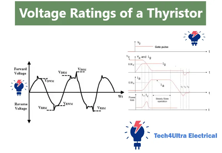
When working with an SCR, one of the most critical aspects to understand is its voltage rating. This includes the peak reverse and forward blocking voltages, commonly labeled as VDRM (maximum repetitive off-state forward voltage) and VRRM (maximum repetitive off-state reverse voltage). These ratings represent the maximum voltages the SCR can withstand in its non-conducting state without allowing current to flow. Going beyond these levels repeatedly can cause the SCR to enter an unintended conducting mode or even get damaged over time.
In addition to those, we have the non-repetitive peak voltages: VDSM (non-repetitive surge forward voltage) and VRSM (non-repetitive surge reverse voltage). These represent the absolute limits the SCR can handle briefly, such as during a lightning strike or startup surge. They’re higher than the repetitive values but should never be treated as operating conditions. They are more like a safety cushion for rare, short-duration spikes.
Another essential concept is avalanche breakdown. If an SCR is exposed to a voltage higher than VRSM or VDSM, the junction can go into avalanche mode, leading to permanent damage. That’s why designers build in safety margins, typically selecting SCRs with voltage ratings 20–30% higher than the expected maximum line voltage. This practice accounts for transients, voltage spikes, and component aging over time.
Bottom line? Respect the rating of SCR—especially the voltage specs. It’s one of the best investments you can make in the reliability of your power system.
Current Ratings of SCR
The current ratings of an SCR are just as critical as its voltage ratings—and often, even more so during startup and fault conditions. Let’s start with the basics: the RMS current (IRMS). This rating tells you the maximum amount of continuous current the SCR can handle without overheating. For example, a typical SCR might have an IRMS of 25A, which means it can safely conduct 25 amps of current in steady-state conditions with proper cooling.
But what about short bursts? That’s where the peak surge current (ITSM) comes in. ITSM refers to the maximum current the SCR can withstand for a very short duration, often one cycle (about 8.3 ms or 10 ms depending on AC frequency). You’ll see values like 200A or even 1000A for ITSM. This rating is crucial during inrush situations, like powering up motors or transformers.
Then there’s the I²t rating, a measure of energy the SCR can absorb during a surge without failing. It’s calculated from the square of the current multiplied by time (I² × t) and is especially important when selecting fuses. Your protective fuse must have an I²t value lower than that of the SCR, ensuring the fuse will blow before the SCR is damaged during a fault.
Finally, two often-overlooked parameters: latching current and holding current. The latching current is the minimum current required to keep the SCR conducting after it’s triggered. The holding current is the minimum current needed to keep it in the ‘on’ state. Drop below this, and the SCR turns off. For small SCRs, these might be in the range of 5–50 mA, while in larger devices, they can reach several amps.
Understanding these thyristor rating parameters ensures you don’t just select an SCR—it ensures you select the right one for the job.
Power Dissipation and Thermal Ratings
Beyond voltage and current, every SCR has limits on how much power it can dissipate without overheating. This is where thermal ratings come into play. The main contributors to power loss in an SCR are conduction losses—caused by voltage drop during the on-state—and switching losses, which occur when the SCR transitions between on and off states, especially at higher frequencies.
Another subtle source of heat is gate triggering power. While usually small (in the milliwatt range), it still contributes to overall power dissipation, especially in designs with multiple SCRs or high-frequency triggering.
This brings us to a crucial aspect of thyristor rating: thermal management. Every SCR has a maximum junction temperature—typically around 125°C to 150°C. To stay below this limit, you need effective heat removal. That’s where heatsinks come in. A properly selected and mounted heatsink ensures heat flows from the SCR’s case to the surrounding air efficiently.
In more demanding environments, you might also need forced air cooling or even liquid cooling. Always consult the datasheet’s thermal resistance values and perform proper thermal calculations to ensure the rating of SCR isn’t exceeded under any operating condition. Overheating is the silent killer of power semiconductors—don’t underestimate it.
Switching Parameters of SCR
When evaluating the rating of SCR, don’t overlook the switching parameters. These define how quickly the device responds to control signals and how fast it can be turned off. The first key metric is the turn-on time, which is the time it takes for the SCR to go from a non-conducting to a conducting state after the gate trigger is applied. This usually happens in a few microseconds (e.g., 1–3 μs), but it varies depending on device size and gate conditions.
Equally important is the turn-off time, also known as commutation time. Once the SCR is conducting, it doesn’t turn off with the gate signal alone. It requires the anode current to drop below the holding current. After that, the SCR needs time to recover before it can block voltage again. This recovery period—often in the range of 10–50 μs—is crucial in circuits using forced or natural commutation.
These timing parameters directly affect your circuit’s speed and switching frequency. If you’re designing for high-speed or high-frequency applications like inverters or choppers, a slower SCR can become a bottleneck. In such cases, you may need specialized fast-switching SCRs or alternative devices like IGBTs or MOSFETs.
Understanding switching time is essential to avoid misfires, incomplete commutation, and unwanted conduction in your circuit. Always match the thyristor rating to the speed demands of your application—it could save you from a host of hard-to-debug problems.
dv/dt and di/dt Ratings
When it comes to properly triggering an SCR and ensuring long-term reliability, two often misunderstood parameters come into play: dv/dt and di/dt. These aren’t just technical buzzwords—they’re critical aspects of thyristor rating that directly affect how your circuit behaves under real-world conditions.
The dv/dt rating refers to the maximum rate of voltage change the SCR can withstand across its terminals while in the off state. If the rate of voltage rise (in volts per microsecond) exceeds this rating, the SCR may turn on unintentionally—even without a gate signal. This phenomenon, known as false triggering, can be dangerous, especially in power circuits. That’s why you’ll often see dv/dt ratings like 100 V/μs or higher in datasheets.
On the other hand, the di/dt rating is about how quickly current can rise through the SCR after it turns on. If the current surge happens too fast, the device’s internal junctions may not spread the current evenly, leading to localized heating and potential damage. Typical safe values range from 50 A/μs to 200 A/μs, depending on the size and design of the SCR.
To protect against dv/dt-triggered turn-on, designers often add snubber circuits—usually a resistor and capacitor in series—across the SCR. These slow down the voltage rise and keep the dv/dt within safe limits. For di/dt protection, gate control circuits must ensure the SCR turns on fully before large current is applied. In high-power circuits, di/dt limiters—like inductors—are used in series with the SCR to smooth out the current rise.
These ratings aren’t optional. Ignoring them can lead to erratic operation or even permanent damage. If you want your SCR-based design to work reliably, mastering these aspects of the rating of SCR is a must.
Practical Selection Guide for SCRs
Choosing the right SCR for your circuit isn’t just about picking the biggest number on the datasheet—it’s about matching the thyristor rating to your actual application needs. And it all starts with understanding how to read those datasheets.
First, look at the voltage ratings—VDRM and VRRM should be at least 20–30% higher than your system’s peak line voltage to handle surges and transients safely. Then check the RMS current (IRMS) and peak surge current (ITSM) ratings. Your chosen SCR should handle your steady-state load comfortably and survive startup surges or fault currents.
Don’t ignore thermal resistance and maximum junction temperature—these guide your heatsink selection. Also, pay attention to di/dt and dv/dt ratings for fast-switching applications like inverters or UPS systems.
Let’s look at some examples:
- Motor Drives: Choose SCRs with high ITSM and strong thermal ratings. Motors have high inrush currents.
- Rectifiers: Prioritize voltage ratings and thermal performance. These often operate near the SCR’s current limits.
- UPS: Fast switching and high reliability matter—focus on dv/dt and commutation times.
- Inverters: Fast turn-off and di/dt tolerance are key. Use snubber networks and select SCRs rated for rapid changes.
Reading the datasheet thoroughly and applying margins isn’t overkill—it’s smart design. The more carefully you match each rating of SCR to your real-world requirements, the more reliable and efficient your system will be.
Common Mistakes in Rating Selection
When selecting an SCR, even experienced designers fall into traps that can cost them time, money, and components. One of the most common mistakes is underrating the device—choosing an SCR with current or voltage limits that are too close to your operating conditions. This leaves no room for unexpected surges or ambient temperature fluctuations, leading to premature failure.
On the flip side, overrating can also be problematic. While it may seem safe to choose the biggest thyristor rating you can find, it can result in unnecessary cost, increased size, and inefficiencies—especially in smaller applications.
Another critical oversight is ignoring surge ratings like ITSM or I²t. These are essential for applications with high inrush current, such as motor starts or capacitor charging.
Finally, thermal mismanagement—underestimating heat dissipation and skimping on heatsinks—can quietly destroy even a well-rated SCR. Always verify thermal margins with real calculations.
Watch Also: Optoisolator Explained: Uses, Benefits & How It Works
Testing and Verification of Ratings
After selecting an SCR, it’s smart practice to verify its thyristor rating under controlled lab conditions—especially in critical designs. For voltage rating verification, use a high-voltage DC source with a series resistor and gradually increase the voltage across the SCR while it remains in the off-state. Monitor leakage current and ensure it stays within datasheet limits below the rated VDRM or VRRM.
To check current handling, apply short controlled pulses through a current source and observe the conduction response using an oscilloscope. Measure how the SCR responds to different load levels and confirm it turns on fully and stays stable under load.
You can also test gate triggering characteristics by applying test pulses with known amplitude and duration. The oscilloscope will help confirm turn-on time and gate sensitivity. This hands-on validation ensures the rating of SCR aligns with real-world conditions and avoids surprises in the field.
Conclusion
By now, you’ve seen that understanding the rating of SCR is not just a technical detail—it’s a design necessity. We’ve covered key rating categories: voltage (VDRM, VRRM), current (IRMS, ITSM, I²t), thermal limits, switching times, and dv/dt and di/dt tolerances. Each plays a vital role in ensuring your SCR works safely and reliably under all conditions.
Here’s a quick checklist for proper thyristor rating usage:
- ✔ Add 20–30% safety margin to voltage ratings
- ✔ Match RMS and surge current ratings to load and startup conditions
- ✔ Verify thermal management with heatsinks or forced cooling
- ✔ Evaluate dv/dt and di/dt specs, and use snubber or inductors if needed
- ✔ Test gate triggering and switching response during prototyping
Respect the specs, and your SCR won’t just survive—it’ll thrive in your application.
FAQs
What is the rating of SCR?
The rating of SCR refers to the electrical and thermal limits that the device can safely handle. This includes voltage ratings like VDRM and VRRM, current ratings such as IRMS and ITSM, switching parameters like turn-on and turn-off times, and thermal limits including maximum junction temperature and power dissipation. These ratings help ensure the SCR performs reliably in specific applications without failing under stress.
How is SCR different from thyristor?
An SCR (Silicon Controlled Rectifier) is actually a type of thyristor. The term “thyristor” is a broader category that includes several devices like SCRs, TRIACs, and GTOs. SCRs are the most common type and are unidirectional, meaning they conduct current in one direction when triggered. So, while all SCRs are thyristors, not all thyristors are SCRs.
What is the surge current rating of SCR?
The surge current rating, or ITSM, indicates the maximum current the SCR can handle for a very short duration, usually one half-cycle of AC (8.3 or 10 ms). It protects the SCR during sudden inrush events like motor startup or transformer energizing. This rating is typically much higher than the continuous current rating and is crucial for avoiding instant burnout.
What is the DV DT rating of SCR?
The dv/dt rating defines the maximum rate of voltage change (in volts per microsecond) that the SCR can tolerate across its terminals in the off-state without triggering unintentionally. If the voltage across the SCR rises too quickly, it may turn on without a gate signal. Designers use snubber circuits to keep dv/dt within safe limits and avoid false triggering.