Contents
Many beginners—and even some experienced engineers—mistakenly believe that the optoisolator, optocoupler, and optical isolator are just different names for the same unimportant component. The truth? Ignoring this tiny device can lead to catastrophic failures in your electronic circuits.
In this article on the Tech4Ultra Electrical website, I’ll walk you through what an optoisolator really is, how it works, and why it’s essential for protecting your electronics from high voltage spikes and signal interference. If you’re aiming to build safer and more reliable circuits, this guide will give you the practical knowledge to do just that.
What is an Optoisolator, Optocoupler, and Optical Isolator?
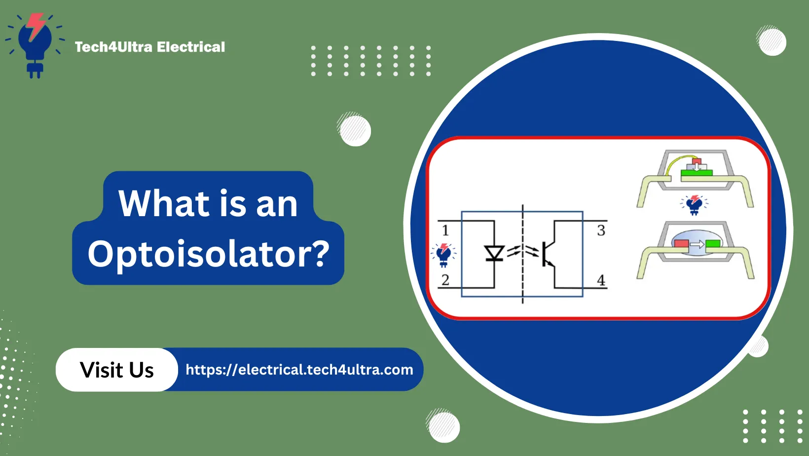
A optoisolator—also known as an optocoupler or optical isolator—is an electronic component that transfers electrical signals between two isolated circuits using light. It typically consists of a light-emitting diode (LED) and a photodetector, such as a phototransistor, housed in a single package. When current passes through the LED, it emits light that activates the photodetector on the other side, allowing signal transmission without direct electrical contact.
Why Electrical Isolation and Signal Integrity Matter
Electrical isolation is critical for protecting sensitive components and users from high voltage levels. By breaking the physical electrical path, optoisolators prevent dangerous current from flowing between systems. They also help maintain signal integrity by minimizing electrical noise, especially in environments with electromagnetic interference (EMI) or fast-switching components.
Where Are Optoisolators Used?
Optocouplers are commonly used in power supplies, microcontroller interfaces, medical equipment, industrial control systems, and data communication. Any application that involves interfacing high-voltage and low-voltage systems—or requires protection against voltage transients—can benefit from a optical isolator.
Read Also: Understanding the Schottky Effect: Field Enhanced Thermionic Emission Explained in Depth
Construction of an Optoisolator
Main Components Inside an Optoisolator
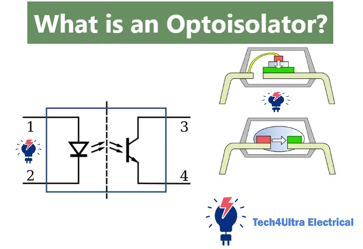
At its core, a optoisolator consists of two primary parts housed within a light-tight package: a light source and a light sensor. The light source is typically a light-emitting diode (LED), while the sensor can be a photodiode, phototransistor, photothyristor, or even a phototriac depending on the application.
When voltage is applied to the LED, it emits infrared or visible light. This light crosses a small gap and strikes the photodetector. The detector responds by generating a corresponding electrical signal—without any direct electrical connection between input and output sides.
Diagram: Basic Structure of an Optocoupler
(Imagine a simplified diagram here showing an LED on the input side emitting light toward a phototransistor on the output side, all within a sealed housing.)
Planar vs Dome Construction
Internally, optoisolators can be constructed using different methods depending on the desired performance and size. In planar construction, both the LED and photodetector are placed flat on a substrate, aligned horizontally. This layout is easier to manufacture and ideal for compact packages.
In dome construction, the LED is positioned facing upward while the photodetector is placed directly above it. A dome-shaped lens or reflective cavity helps focus the emitted light. This arrangement improves light coupling efficiency, making it more effective for high-speed or low-signal applications.
The construction style impacts how well the optocoupler performs in terms of speed, sensitivity, and isolation voltage. Knowing the layout helps you choose the right optical isolator for your circuit design.
Operating Principle of Optoisolators
From Electricity to Light: The LED’s Role
In a optoisolator, the process begins with the LED on the input side. When a voltage is applied, current flows through the LED, causing it to emit light—usually infrared. This light is confined within the package, targeting the photodetector on the output side. The key here is that the electrical signal is now converted into a light signal, eliminating any direct electrical path between input and output.
Light Detection: How Photodiodes and Phototransistors Respond
The light from the LED strikes a photodiode or phototransistor. A photodiode is usually reverse-biased, meaning it resists current flow under normal conditions. However, when exposed to light, it generates a photocurrent proportional to the light intensity. This photocurrent flows even though the diode is reverse biased, a behavior known as the photoelectric effect.
In contrast, a phototransistor works like a normal transistor but with light replacing the traditional base current. The more light it receives, the more current it allows to flow from collector to emitter. It’s extremely sensitive, making it ideal for amplifying weak signals.
Dark Current, Light Intensity, and CTR
Even without light, photodiodes exhibit a tiny leakage current called “dark current.” It’s minimal but important to understand when designing sensitive systems. As light intensity increases, the output current rises accordingly. This relationship defines how the optocoupler responds to varying input levels.
One of the most important parameters in a optical isolator is the Current Transfer Ratio (CTR). It’s defined as the ratio of output current (from the phototransistor) to input current (through the LED), usually expressed as a percentage. For instance, a CTR of 100% means the output current equals the input current. High CTR values indicate efficient signal transfer.
Types of Optoisolators
Phototransistor-Based Optoisolators
The most common type of optoisolator is based on a phototransistor. It offers good response time, moderate gain, and is cost-effective for general-purpose applications like switching, microcontroller interfacing, and signal isolation in low-speed circuits. These devices work well when logic-level compatibility and low noise are important.
Photo-Darlington Optoisolators
A photo-Darlington optocoupler uses two transistors connected in a Darlington pair configuration to provide higher gain. This significantly amplifies the output current, making it suitable for detecting very low input currents. However, the response time is slower compared to a regular phototransistor, which limits its use in high-speed circuits. Ideal use cases include low-frequency signal detection and high-impedance input circuits.
Photo-SCR Optoisolators
The photo-SCR (Silicon Controlled Rectifier) variant is used primarily in AC switching circuits. It conducts only in one direction and latches on when triggered by light. Once turned on, it stays on until the current drops below a certain threshold. It’s commonly found in solid-state relays and industrial AC controls.
Photo-Triac Optoisolators
For AC control across both halves of the waveform, the photo-Triac optoisolator is the go-to solution. It can control AC loads directly and is often used in light dimmers, motor controls, and household appliances. These devices trigger in both directions, offering complete AC cycle control, but may require snubber circuits for inductive loads.
Slotted and Reflective Optoisolators
Slotted optoisolators, also known as interrupters, have an open slot between the LED and detector. When an object blocks the slot, the light is interrupted, changing the output. These are widely used in position sensing and encoder systems.
Reflective optoisolators operate by bouncing light off a nearby object back to the detector. They are used where physical slots aren’t practical, like detecting proximity or motion over a surface.
Comparing the Types
- Phototransistor: General-purpose, moderate speed, low cost.
- Photo-Darlington: High gain, low-speed, sensitive input detection.
- Photo-SCR: Unidirectional AC switching, latching behavior.
- Photo-Triac: Bidirectional AC switching, robust load control.
- Slotted: Ideal for motion detection and object counting.
- Reflective: Suitable for surface tracking and close-range sensing.
Choosing the right optocoupler or optical isolator depends on your application’s voltage, current, speed, and environmental constraints.
Advantages and Limitations
Why Use Optoisolators?
One of the biggest advantages of a optoisolator is its ability to provide galvanic isolation. This means there’s no direct electrical connection between input and output, making it extremely useful in protecting low-voltage logic circuits from high-voltage spikes or ground loops.
Noise immunity is another major benefit. By transferring signals through light, optocouplers avoid problems like electromagnetic interference (EMI) or signal distortion, which are common in industrial and automotive environments.
Add to that the compact design—these components are small, efficient, and easy to integrate into PCBs without taking up much space. This makes optical isolators ideal for densely packed electronics like power supplies, inverters, and communication devices.
Limitations to Consider
Despite their many strengths, optoisolators do have some drawbacks. One key issue is the Current Transfer Ratio (CTR), which can vary widely between devices and tends to degrade over time or under temperature extremes. This inconsistency can affect signal reliability in precision circuits.
Another challenge is speed. Standard phototransistor-based optocouplers are relatively slow compared to modern digital isolators, limiting their use in high-frequency applications.
Lastly, temperature dependence affects both the LED and detector. Performance can drift in hot or cold environments, which may require additional circuit compensation.
In short, while optoisolators offer reliable isolation and protection, careful design is needed to work around their limitations.
Practical Applications of Optoisolators
Switch Mode Power Supplies (SMPS)
In modern Switch Mode Power Supplies (SMPS), optoisolators play a critical role in maintaining voltage regulation and system protection. They are commonly used in the feedback loop to transfer output voltage information back to the primary side controller without a direct electrical connection. This ensures safe regulation while keeping primary and secondary circuits isolated.
Microcontroller Interfaces and PLCs
When connecting microcontrollers to external components, isolation is often essential—especially when interfacing with higher-voltage devices. Optocouplers serve as perfect gatekeepers, preventing reverse currents or voltage spikes from damaging the logic-level circuitry.
In Programmable Logic Controllers (PLCs), optical isolators protect input/output ports and enhance system reliability. They allow the PLC to safely monitor and control a wide range of external equipment operating at different voltages and noise levels.
Solid-State Relays and Automation
Solid-state relays (SSRs) rely heavily on photo-Triac and photo-SCR optoisolators to trigger AC loads without mechanical parts. These components offer silent switching, fast response, and longer lifespan—ideal for industrial automation where durability and safety are priorities.
Audio Systems and Power Supplies
In audio applications, optoisolators help prevent ground loops that introduce hum or noise. They’re also used in volume control and signal routing, especially in analog/digital hybrid systems.
Likewise, power supplies benefit from optocouplers for fault isolation, protection circuits, and efficient feedback regulation. Their ability to block transients while ensuring stable signal transmission makes them indispensable.
From factory floors to your home entertainment system, optical isolators silently work to keep signals clean and systems protected.
Watch Also: SCR turn-on time Explained: Complete Guide to Switching and Turn‑Off Characteristics
How to Choose the Right Optoisolator
Key Parameters to Consider
When selecting a optoisolator, a few key specifications can make or break your circuit design. First up is the Current Transfer Ratio (CTR). This tells you how efficiently the input current is converted to output current. A higher CTR means better signal transfer, but beware—it can vary with temperature and device aging.
Isolation voltage is another critical factor. This defines the maximum voltage difference the optocoupler can safely handle between its input and output sides. Applications involving high-voltage switching or safety compliance often require ratings above 5,000 volts.
Don’t overlook speed, especially if you’re working with fast digital signals. Standard phototransistor types might top out around 10 kHz, while high-speed logic optoisolators can handle MHz-level signals. Always check the rise and fall times in the datasheet.
Digital vs Analog Applications
For digital applications—like interfacing microcontrollers or signal switching—choose an optical isolator with fast switching times and TTL-compatible output levels.
Analog applications, on the other hand, demand linearity and low noise. Specialized linear optocouplers with photodiode-feedback configurations are designed for such tasks, like audio signal isolation or precision voltage feedback.
Matching the optoisolator to your circuit’s speed, voltage, and signal type ensures reliable performance and long-term stability.
Conclusion
Optoisolators, also known as optocouplers or optical isolators, are more than just components—they’re guardians of circuit safety and reliability. Whether you’re designing a power supply, automating an industrial system, or simply isolating a microcontroller input, choosing the right optoisolator can make all the difference.
By understanding their construction, operation, and application-specific variations, you gain the insight to protect your designs from voltage spikes, noise, and unexpected failures. From simple signal transfer to complex system protection, optoisolators are small parts with big responsibilities.
FAQs
What is the working principle of an optocoupler?
A optocoupler works by converting an electrical signal into light using an internal LED. This light is then detected by a photodetector—such as a phototransistor or photodiode—on the output side. The detector converts the light back into an electrical signal. This allows signal transmission while keeping input and output electrically isolated.
How does an optical isolator work?
An optical isolator operates on the principle of light-based signal transfer. The input circuit powers an LED, emitting light that travels across an internal gap to a photodetector. The light triggers the detector to produce a corresponding output signal, maintaining electrical isolation between the circuits. This helps protect low-voltage systems from high-voltage interference.
What is opto isolation and what is the main advantage?
Opto isolation is the method of using light to transfer signals between circuits that should not share a direct electrical connection. The main advantage is galvanic isolation, which prevents electrical noise, surges, and ground loop issues from damaging sensitive components. It’s widely used for protecting microcontrollers, communication lines, and control interfaces.
How does an Opto Triac work?
An Opto Triac contains an LED and a light-activated triac in one package. When the LED is energized, it emits light that triggers the triac to conduct. This allows AC current to flow through the output circuit. Opto Triacs are commonly used in solid-state relays for switching AC loads with no mechanical contacts.
What is the work of Opto?
An opto, or optoisolator, functions as a bridge between two separate circuits by using light to transmit signals without a direct electrical connection. Its main job is to isolate and protect low-voltage control systems from high-voltage loads, preventing damage due to surges or ground loops.
What is the working principle of TRIAC?
A TRIAC (Triode for Alternating Current) is a bidirectional semiconductor device that can conduct current in both directions when triggered. It operates by receiving a small gate signal, which switches it on, allowing it to control large AC loads like motors or lighting circuits with high efficiency.
Is a TRIAC output AC or DC?
The output of a TRIAC is strictly AC. Since TRIACs are designed to conduct in both directions, they are specifically used in AC power control applications. They do not function properly with DC because there is no natural zero-crossing to turn off the current flow.
How to check if a TRIAC is working?
To check a TRIAC, you can use a multimeter with diode-testing mode. Measure the resistance between the terminals (MT1, MT2, and gate). If it shows low resistance in both directions or doesn’t trigger when a gate signal is applied, the TRIAC may be faulty. For accurate testing, simulate real conditions by applying a small gate current and observing the conduction across MT1 and MT2.
What is a TRIAC generally used for?
TRIACs are commonly used for controlling AC power. Typical applications include dimming lights, speed control of AC motors, and electronic switching in household appliances. Their ability to handle both halves of an AC waveform makes them perfect for efficient and silent power control.
2 thoughts on “SCR turn-on time Explained: Complete Guide to Switching and Turn‑Off Characteristics”