Contents
Have you ever struggled with an annoying hum in your audio recordings or interference in your communication systems? Many people mistakenly believe that filters are only for adjusting colors in photos or enhancing bass in music. In reality, the band-stop filter, also known as a notch filter, is a powerful tool for eliminating unwanted frequencies from electronic signals. In this article on the Tech4Ultra Electrical website, you’ll discover how it works, where it’s used, and why it’s an essential part of any engineer’s toolkit. By the end, you’ll know exactly how to use it to clean up your signals and optimize your systems.
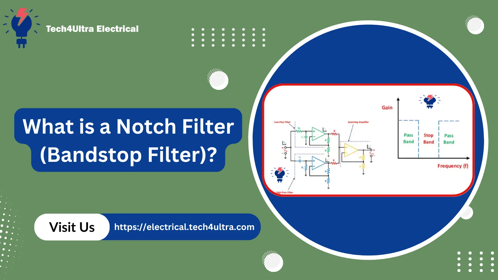
What is a Notch Filter (Bandstop Filter)?
The first time I heard about a notch filter, I was editing audio for a podcast. There was this annoying hum—right at 60 Hz—that just wouldn’t go away. No matter how much EQ tweaking I did, it stayed. That’s when someone told me, “Just use a notch filter.” And honestly? It felt like magic.
A notch filter—also called a band-stop filter—is a type of signal processing tool used to remove or “notch out” a specific range of frequencies while letting everything else pass through untouched. It’s like telling your system, “Mute this narrow band and leave the rest alone.”
What Makes It Unique?
Unlike low-pass or high-pass filters that cut off frequencies below or above a certain threshold, a notch filter targets a very narrow band. It’s super precise.
- It’s highly selective — perfect for eliminating a single frequency, like electrical hum (50/60 Hz).
- It doesn’t mess with the rest of your signal — you lose almost nothing outside the notched band.
- It’s widely used in audio processing, biomedical signals (like ECG), and RF communications.
How It Actually Works
Let’s simplify this: imagine your signal is a road, and you want to block just one lane (a specific frequency range). The notch filter acts like a barrier that only affects that lane.
There are two primary types:
- Active notch filters — use op-amps and resistors; great for low-frequency signals.
- Passive band-stop filters — use capacitors and inductors; more common in high-frequency applications.
And yep, I made the mistake once of using a passive design for a low-frequency hum—it barely worked. Lesson learned: match the filter type to the application.
When Should You Use One?
If you’re:
- Dealing with power line noise in audio (like I was)
- Removing interference in communication channels
- Cleaning up EEG or ECG signals in biomedical devices
…then a band-stop filter is your best friend.
“In engineering, the best solution is often the simplest one. And notch filters are a simple answer to a noisy problem.”
Stick around — next, I’ll show you how to design one from scratch (without the math headaches).
Read Also: Filter Bank in Signal Processing: Types, Applications, and Modern Advances Explained
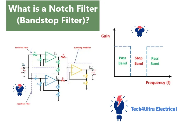
Understanding the Filter Behavior
Stop-band, Pass-band, and Bandwidth
To understand how a notch filter or band-stop filter works, you need to know three key terms: stop-band, pass-band, and bandwidth.
The stop-band is the narrow frequency range that the filter aims to suppress. Anything within this range gets significantly reduced or completely removed. The pass-band refers to the frequencies outside this range that the filter allows to pass with minimal attenuation. The bandwidth is simply the width of the stop-band — that is, the range of frequencies that are being blocked.
Notch Depth and Attenuation
Notch depth refers to how much the filter can reduce the amplitude of the unwanted frequency. A deeper notch means stronger rejection. This is often represented in decibels (dB), showing how effectively the filter attenuates the signal. Attenuation is the technical term for signal reduction — and in this case, we want it to be as high as possible within the stop-band.
Comparison with Band-pass and Low/High-pass Filters
Unlike a band-pass filter which allows only a specific range of frequencies to pass, or low-pass and high-pass filters that allow either low or high frequencies, a band-stop filter removes just a narrow slice and keeps everything else. It’s more like carving out a single unwanted frequency than building a wall against large parts of the spectrum.
Types of Band-Stop Filters
Narrow-band vs Wide-band
When it comes to band-stop filters, the most important distinction is between narrow-band and wide-band types. A narrow-band filter is designed to eliminate a very specific and small frequency range—often used to remove things like electrical hum at 50 or 60 Hz. This is typically what we refer to as a notch filter.
On the other hand, a wide-band band-stop filter targets a broader range of frequencies. It’s more common in communication systems where you want to block out an entire band of interference or unwanted signals, rather than just a single frequency.
Passive vs Active Filters
Passive filters use only resistors, capacitors, and inductors. They don’t need a power supply, which makes them simpler and more stable, especially at high frequencies. However, they can’t amplify signals and are often less precise at low frequencies.
Active filters incorporate components like operational amplifiers (op-amps). These can amplify signals and provide much sharper cutoffs. They’re especially useful in audio applications and low-frequency electronics where precision matters.
RC, LC, and Op-Amp-Based Notch Filters
There are several practical designs for notch filters, depending on the application:
- RC filters: Use resistors and capacitors. Great for simple, low-cost, low-frequency needs.
- LC filters: Use inductors and capacitors. More suited for high-frequency filtering but can be bulky.
- Op-amp-based filters: These active notch filters offer the best control over frequency, depth, and bandwidth. They’re ideal for precision work like audio signal processing or instrumentation.
Choosing the right type of band-stop filter depends on your specific needs—do you need simplicity, precision, or performance at high frequencies?
Key Parameters Explained
Cut-off Frequencies (fL and fH)
Every band-stop filter operates between two essential limits: the cut-off frequencies. These are labeled as fL (lower cut-off) and fH (higher cut-off). Frequencies below fL and above fH pass through the filter with little to no attenuation, while anything between them gets significantly suppressed. Think of them as the entry and exit points of the stop-band.
Centre Frequency and Geometric Mean
The centre frequency (fc) is the midpoint of the stop-band. It’s often calculated using the geometric mean of the cut-off frequencies:
fc = √(fL × fH)
This method provides a more accurate center point for logarithmic frequency scales, especially important in RF and audio applications.
Bandwidth and Q Factor
Bandwidth is the range of frequencies the notch filter attenuates—calculated simply as fH - fL. A narrow bandwidth means precise targeting of unwanted signals, while a wide bandwidth removes broader ranges.
Q factor (quality factor) describes how “sharp” or selective the notch is. A higher Q means a deeper, narrower notch. It’s critical in designing filters for applications like audio noise reduction or biomedical signal isolation.
Transfer Function and Poles/Zeros
The transfer function of a band-stop filter is a mathematical representation of how it affects different frequencies. It shows the ratio of output to input signal in the frequency domain.
Poles and zeros are key to shaping this function. Zeros define where the signal is blocked (the notch), and poles determine how the response behaves near those frequencies. Together, they dictate the depth and sharpness of the filter.
Design Methodology with Examples
Twin-T Network Design
One of the most classic and efficient ways to build a notch filter is the Twin-T network. This passive design uses two T-shaped branches—one made with resistors and capacitors in series and the other with a parallel configuration. When combined, they cancel out a specific center frequency due to phase shift and attenuation.
The Twin-T filter is simple and ideal for fixed-frequency applications like removing 60 Hz power line noise. But keep in mind—it’s sensitive to component tolerances and might need fine-tuning in practice.
RC Narrow-Band Circuit
A basic RC notch filter uses resistors and capacitors to form a frequency-selective network. It’s perfect for low-frequency applications. You can adjust the notch frequency by varying R or C. While not very sharp (low Q factor), it’s a great educational tool or solution for hobby projects.
Here’s a quick example:
- Choose R = 10 kΩ and C = 0.1 µF
- Use the formula:
f = 1 / (2πRC) - Resulting notch frequency ≈ 159 Hz
Op-Amp Implementation Using Summing Amplifier
Want more precision? Use an op-amp-based notch filter. One popular design involves a summing amplifier with a feedback loop that creates the desired attenuation at the center frequency. You can easily control gain, Q, and bandwidth with this setup.
It’s especially effective for dynamic audio systems or precision instruments. Plus, op-amps are cheap and widely available, making this an accessible approach for most designers.
Step-by-Step Calculation Example
Let’s walk through an example using a Twin-T passive band-stop filter targeting 60 Hz:
- Start with the center frequency formula:
fc = 1 / (2πRC) - Choose C = 0.1 µF
- Solve for R:
R = 1 / (2π × 60 × 0.1×10⁻⁶)≈ 26.5 kΩ - Use standard resistor values and test via simulation
Simulation Tools and Software Usage
Before building your filter, it’s smart to simulate it. Free tools like LTspice, TINA-TI, or Falstad Circuit Simulator let you test frequency response, identify issues, and make changes without wasting components.
Use Bode plots to examine the stop-band, attenuation depth, and pass-band behavior. You can even model component tolerances to see how they affect real-world performance.
Pro tip: always simulate before soldering. It saves hours of frustration—believe me, I’ve learned that the hard way.
Whether you’re using a basic RC circuit or a precise op-amp design, mastering the band-stop filter starts with solid planning and real-world testing.
Common Applications of Notch Filters
Power-line Interference Removal (50/60 Hz)
One of the most common uses of a notch filter is to eliminate power-line interference. In many countries, the electrical grid operates at either 50 Hz or 60 Hz, and this frequency often creeps into sensitive audio and signal processing circuits. By applying a narrow band-stop filter centered at that frequency, you can clean up your signal without affecting the rest of the data.
Audio System Feedback Elimination
Ever heard that awful squeal from a microphone and speaker setup? That’s audio feedback, and it happens when the microphone picks up sound from the speaker and loops it. A notch filter is often used in audio systems to eliminate the exact frequency where the feedback occurs—without compromising the overall sound quality. It’s a lifesaver for live performances and studio work alike.
EMI/RFI Suppression in Communication Systems
In RF and communication systems, electromagnetic interference (EMI) and radio frequency interference (RFI) can disrupt performance. A band-stop filter can be tuned to block these unwanted frequencies, improving signal integrity and reducing noise in wireless and data transmission environments.
Medical Electronics (ECG, EEG)
In biomedical electronics, especially ECG and EEG monitoring systems, noise from power lines or other devices can obscure critical physiological signals. A well-designed notch filter helps remove this interference, ensuring clean and accurate readings without losing the essential data.
Troubleshooting & Optimization Tips
Dealing with Bandwidth Issues
One of the most common challenges with a band-stop filter is getting the bandwidth just right. If it’s too wide, you might lose important signal content. Too narrow, and you may not fully suppress the unwanted frequency. Always start by clearly defining your application’s stop-band requirements and use simulation tools to fine-tune the component values accordingly.
Minimizing Component Tolerance Effects
Component tolerances can really mess with a notch filter’s performance, especially in Twin-T and RC circuits. A 5% resistor or capacitor may seem fine on paper but can shift your notch frequency off target. Use 1% or better tolerance components whenever possible, and if budget allows, test each component before soldering them into the circuit.
Stability in Op-Amp Based Filters
Op-amp notch filters offer more flexibility, but they come with their own set of issues. Poor layout, insufficient power supply decoupling, or selecting an op-amp with inadequate bandwidth can lead to instability. To optimize stability:
- Use bypass capacitors close to the op-amp pins
- Choose op-amps with adequate slew rate and gain-bandwidth product
- Keep feedback paths short and clean
With a bit of care and smart troubleshooting, your notch filter can deliver precise, stable performance—every time.
Watch Also: SCR turn-on time Explained: Complete Guide to Switching and Turn‑Off Characteristics
Advanced Design Techniques
Active Twin-T Design with Variable Notch
The classic Twin-T notch filter is great for fixed-frequency applications, but what if you need a filter that adapts? That’s where the active Twin-T design comes in. By incorporating variable resistors (like potentiometers) or voltage-controlled components into the network, you can create a variable notch filter.
This approach is perfect for applications like tunable audio filters or test equipment where the unwanted frequency might change. You maintain the sharp attenuation of the Twin-T structure while gaining the flexibility of adjustment, thanks to the added op-amp stage for buffering and gain control.
Adaptive Notch Filters Using Digital Techniques
Need real-time adaptability? That’s where adaptive notch filters come in. These are implemented in digital signal processing (DSP) systems and can track and suppress dynamically changing interference—like vibrations, power harmonics, or motor noise.
They use algorithms like LMS (Least Mean Squares) to continuously adjust filter parameters based on incoming data. It’s like giving your filter a brain—it learns and adapts to cancel noise precisely as it appears. This is commonly used in control systems, industrial monitoring, and real-time biomedical applications.
Using Band-Stop Filters in DSP
Digital band-stop filters are common in software-based systems where flexibility is key. Tools like MATLAB, Python with SciPy, or dedicated DSP chips allow you to design filters using high-order IIR or FIR techniques.
You can model the exact notch frequency, bandwidth, and Q factor, then test and implement the design with minimal hardware. Plus, it’s easy to update the filter if system requirements change—no soldering required!
Whether you go analog or digital, mastering these techniques unlocks the full potential of the notch filter.
Conclusion
So, what have we learned about the notch filter or band-stop filter? It’s a simple yet powerful tool used to eliminate unwanted frequencies without affecting the rest of your signal. From Twin-T networks to digital adaptive filters, the design options are versatile, and so are the applications—whether it’s removing 60 Hz hum in audio, cleaning up ECG signals, or filtering interference in RF systems.
Design-wise, remember the key factors: cut-off frequencies, bandwidth, and Q factor. Use high-tolerance components, simulate before you build, and choose active or passive designs based on your needs. Digital options open the door to dynamic and adaptive filtering when analog can’t keep up.
So when should you pick a band-stop filter over a low-pass or band-pass filter? Easy—use it when you want to block just one annoying frequency while keeping everything else. It’s the surgical knife in your signal-processing toolkit.
In the end, knowing when and how to use a notch filter is a small step that can make a huge difference in signal clarity and system performance.
FAQs About Notch Filters
What is the Difference Between Band-Reject and Band-Stop?
Honestly, there’s no functional difference between a band-reject filter and a band-stop filter. Both terms describe the same thing: a filter that blocks a specific range of frequencies while allowing others to pass. However, in casual usage, people often refer to a very narrow band-stop filter as a notch filter, especially when it’s targeting a single interference frequency like 50 or 60 Hz.
How to Choose the Right Filter for My Circuit?
Choosing the right notch filter depends on your signal requirements:
- Need to remove a single, narrow frequency? Go with a narrow-band notch filter.
- Working with low frequencies? Try an RC filter or an active op-amp design.
- Handling high frequencies? Use an LC filter or consider digital filtering for more flexibility.
Also, don’t forget to factor in Q factor, notch depth, and component tolerance—these can make or break the filter’s effectiveness.
Can a Notch Filter Be Tunable?
Yes! A tunable notch filter is absolutely possible. You can make it tunable by adding variable resistors, trimmer capacitors, or using voltage-controlled components. In digital systems, it’s even easier—just adjust your coefficients in the code or DSP software.
Tunable filters are especially useful in systems where interference may shift over time, like in wireless communication or test and measurement setups.
Whether analog or digital, tunable band-stop filters give you the power to adapt in real-time and keep your signals clean.
What is the Transfer Function of a Band-Stop Filter Circuit?
The transfer function of a band-stop filter describes how the output signal varies with frequency relative to the input. Mathematically, it’s usually written as a ratio of polynomials in the Laplace domain (s-domain) or frequency domain (jω). It defines the location of the notch and how sharply the filter attenuates the signal in the stop-band. For example:
H(s) = (s² + ω₀²) / (s² + (ω₀/Q)s + ω₀²)
Where ω₀ is the notch frequency and Q is the quality factor.
What is a Notch Filter in a Circuit?
A notch filter is a special type of band-stop filter that removes a very narrow range of frequencies. In circuits, it’s implemented using RC, LC, or op-amp configurations. It’s commonly used to eliminate specific types of interference, such as 50/60 Hz noise from power lines in audio or biomedical equipment. The rest of the signal remains mostly unaffected, which makes it perfect for applications needing high precision.
What is a Band-Stop Filter Used For?
A band-stop filter is used to block or attenuate signals within a specific frequency range, known as the stop-band, while allowing frequencies outside this range to pass through. It’s commonly applied in:
- Audio systems – to eliminate feedback or hum
- Power electronics – to filter out 50/60 Hz interference
- Communication systems – for EMI/RFI suppression
- Medical electronics – for removing power noise from ECG/EEG signals
What is the Transfer Function of a Filter in a Circuit?
The transfer function in any circuit filter shows the mathematical relationship between the input and output signals as a function of frequency. It helps engineers analyze how the filter will behave across the frequency spectrum. In the case of a band-stop filter, it helps define how deep the notch is and how narrow or wide the rejection band will be. This function is essential for designing filters that perform precisely as needed.
5 thoughts on “Understanding the Schottky Effect: Field Enhanced Thermionic Emission Explained in Depth”