
Contents
Have you ever wondered why some electronic devices don’t work properly even though they’re assembled correctly? The answer might lie in resistance measurement. In this article on the Tech4Ultra Electrical website, you’ll learn how to accurately perform measurement of resistance using tools like a multimeter and an ohmmeter. By the end, you’ll know how to identify faulty components, avoid common mistakes, and confidently troubleshoot electrical issues with precision.
Understanding resistance measurement is key to mastering electronics. In simple terms, electrical resistance is the opposition that a material offers to the flow of electric current. It’s measured in ohms (Ω), and every component in an electrical circuit—wires, resistors, or even the human body—has some level of resistance.
Accurate measurement of resistance isn’t just a theoretical exercise—it’s essential for real-world applications. Whether you’re fixing a faulty appliance, designing a circuit, or testing components, knowing how to measure resistance correctly helps you identify problems like broken wires, damaged resistors, or poor connections. Without it, diagnosing issues becomes a guessing game.
Resistance measurement is widely used in both electrical and electronic circuits. From checking the health of a heating element in a toaster to verifying sensor functionality in a car, technicians and engineers rely on tools like a multimeter or ohmmeter to ensure everything works as intended. Without resistance testing, reliable electronics would be impossible.
Understanding Electrical Resistance
Electrical resistance refers to the opposition a material presents to the flow of electric current. This opposition causes electrical energy to be converted into heat, which is why devices like toasters and heaters get warm. The standard unit used to measure this resistance is the ohm, symbolized by the Greek letter Ω. When we say a resistor has a value of 100 ohms, we mean it resists the current flow at that specific rate.
The amount of resistance in a material depends on several factors, especially the type of material and its temperature. Conductors like copper have low resistance, allowing electricity to flow easily. Insulators like rubber have high resistance, effectively blocking current. Temperature also plays a crucial role—most materials increase in resistance as they get hotter, which is important to consider in devices that heat up during use.
In the real world, **resistors** are components designed specifically to provide a set amount of resistance. They’re found in nearly every electronic device. **Wires**, on the other hand, are designed to have very low resistance, so they can carry current efficiently. Understanding these concepts is vital before you pick up a multimeter or ohmmeter for your next resistance measurement task.
Read Also: What is a Megger? Working Principle and Applications
Tools Used in Measuring Resistance
Multimeter (Analog and Digital)
The most common tool for resistance measurement is the multimeter. Whether analog or digital, a multimeter can measure voltage, current, and resistance. When set to the resistance (Ω) mode, it sends a small current through the component and calculates its electrical resistance based on the voltage drop.
Analog multimeters use a moving needle to display values and are valued for their simplicity. However, they can be hard to read precisely and are less accurate.
Digital multimeters (DMMs) display readings on a screen, offer higher accuracy, and are easier to use. Some even auto-range and come with safety features for high-voltage environments.
Pros:
- Versatile—can measure multiple values.
- Widely available and affordable.
- Easy to use for beginners and professionals.
Cons:
- May not measure very low resistance accurately.
- Cheap models can lack precision and durability.
Ohmmeter
The ohmmeter is a dedicated device for resistance measurement. It operates on a similar principle as a multimeter but focuses solely on measuring electrical resistance. It’s ideal for tasks that require consistent resistance checks, such as in educational labs or maintenance routines.
Ductor Meter & ESR Meter
Ductor meters are specialized for measuring extremely low resistances—like in grounding systems or contact points—down to micro-ohms. ESR meters, on the other hand, are used for checking capacitors’ internal resistance (Equivalent Series Resistance), which is crucial in electronics repair, especially for power supplies.
Each of these tools has its place, depending on the type and sensitivity of the resistance measurement you’re conducting.
Methods of Measuring Resistance
Two-Terminal Method
The two-terminal method is the most commonly used approach for basic resistance measurement, especially when using a multimeter or ohmmeter. In this method, two probes are connected to both ends of the component. A small current is passed through the part, and the voltage drop is measured to calculate the electrical resistance.
This setup is quick, easy, and sufficient for most household and electronic testing tasks. However, it’s not always accurate—especially when measuring very low resistances. Why? Because the resistance of the test leads and contact points gets included in the measurement, sometimes adding significant error.
Limitations:
- Not ideal for low-resistance components (below 1 ohm).
- Subject to lead and contact resistance errors.
- Less accurate in high-precision applications.
Four-Terminal (Kelvin) Method
For high-accuracy resistance measurement, especially in industrial and laboratory settings, the four-terminal method—also known as the Kelvin method—is preferred. It uses two wires to source current and two separate wires to sense voltage, effectively removing the influence of lead and contact resistances.
Working principle: By separating the current path from the voltage sensing path, the device measures only the actual voltage drop across the component, excluding the resistance of the test leads. This results in a much more precise measurement of resistance.
Advantages:
- Highly accurate, even for micro-ohm-level measurements.
- Eliminates contact and lead resistance effects.
- Essential for precision electronics and calibration labs.
Industrial applications: You’ll find the Kelvin method used in motor winding tests, PCB trace resistance checks, and battery connection integrity verification. It’s a go-to in scenarios where precision matters more than speed.
Watch Also: Differential Protection of Generators: Complete Guide
Bridge Methods for Precision Measurement
Wheatstone Bridge
The Wheatstone Bridge is a classic method for high-precision resistance measurement, especially for unknown resistors. It consists of a simple circuit with four resistors arranged in a diamond shape, a voltage source, and a galvanometer at the center to detect balance.
Circuit design: The bridge has two known resistors (R1 and R2), one variable resistor (R3), and one unknown resistor (Rx). When the bridge is balanced—meaning no current flows through the galvanometer—the ratio of resistances on both sides is equal:
R1 / R2 = Rx / R3
From this, you can calculate the unknown resistance:
Rx = (R1 × R3) / R2
Step-by-step example:
- R1 = 100 ohms
- R2 = 200 ohms
- R3 = 150 ohms (adjusted until the bridge is balanced)
Then, the unknown resistance measurement becomes:
Rx = (100 × 150) / 200 = 75 ohms
Wheatstone bridges are extremely accurate and still widely used in sensor applications like strain gauges and temperature transducers.
Kelvin Bridge
When you’re working in the world of very low resistances—think under 1 ohm—the Kelvin Bridge takes over. It’s a modified version of the Wheatstone Bridge, specially designed to eliminate the error caused by lead and contact resistances.
This makes it perfect for industrial use cases such as checking circuit board traces, fuse links, or high-current connectors. Because of its accuracy, the Kelvin Bridge is often used in combination with a ductor meter for micro-ohm-level resistance measurement.
Its ability to provide highly precise measurement of resistance makes it indispensable for advanced electronics and electrical maintenance work.
Factors Affecting Measurement Accuracy
When performing a resistance measurement, accuracy is everything. But even with the best multimeter or ohmmeter, several factors can skew your results if not properly managed.
Contact and lead resistance: One of the most common issues is the resistance introduced by the test leads and connection points. In low-resistance measurements, even a few milliohms of lead resistance can completely throw off the reading. This is especially problematic in the two-terminal method. Using four-terminal or Kelvin methods can minimize this error.
Instrument calibration: Over time, measurement tools can drift from their original calibration. Regularly calibrating your instruments ensures they give accurate results. Always follow the manufacturer’s recommended calibration intervals—especially if you rely on the tool for critical tasks.
Ambient temperature and thermal EMF: Resistance in most materials increases with temperature. So, a change in room temperature, or heat generated by the component itself, can affect readings. Additionally, when two different metals are joined (as in test leads), temperature differences can generate small voltages—called thermal EMF—that interfere with low-level resistance measurement.
Signal noise: Electrical noise from nearby equipment or poor grounding can also corrupt readings. This is particularly noticeable in sensitive low-resistance or high-precision environments. Using shielded cables, proper grounding, and differential measurement setups can help reduce interference.
Being aware of these factors and compensating for them where possible will make your measurement of resistance more accurate and reliable—especially in professional or industrial applications.
How to Measure Resistance: Step-by-Step Guide
Performing a reliable resistance measurement is easy—if you know the proper steps and safety checks. Here’s how to do it right using a multimeter or ohmmeter.
Step 1: Safety Precautions
Never measure electrical resistance in a live circuit. Always disconnect the power source before beginning. If you’re unsure, double-check with the voltage setting on your multimeter first. Also, discharge any capacitors in the circuit—they can store charge and give false readings or damage your meter.
Step 2: Setting Up the Meter
Turn the rotary switch on your multimeter to the resistance (Ω) setting. If you’re using a manual range model, select a range higher than the expected resistance. Auto-ranging models will adjust automatically.
Step 3: Connecting the Leads Correctly
Insert the black probe into the COM (common) port and the red probe into the port labeled Ω. Ensure the probes are firmly connected and clean at the tips to avoid contact resistance.
Step 4: Reading and Interpreting Values
Touch the probe tips to the two ends of the component or wire being tested. For a known resistor, compare the reading to its color code. A perfect match isn’t always expected—tolerances of ±1% to ±10% are normal. A reading of “OL” (over limit) means the resistance is too high or the component is open (broken).
Step 5: Troubleshooting Errors
- Check lead connections and cleanliness if you get fluctuating readings.
- Verify the circuit is powered off—measuring resistance in a live circuit can give incorrect values.
- If values seem off, check for heat in the component or retry with a different range.
Follow these steps and your measurement of resistance will be accurate, safe, and stress-free.
Use Cases and Practical Applications
Resistance measurement isn’t just a theory you learn in textbooks—it’s a practical skill used daily by technicians, engineers, and hobbyists. Let’s look at where this knowledge really matters.
Measuring wire and cable resistance: Long or coiled wires can develop high electrical resistance over time, especially in power applications. Using a multimeter or ductor meter, you can check the resistance of a cable to ensure it hasn’t degraded. Higher-than-normal readings may indicate internal damage or corrosion, which could lead to power loss or overheating.
Verifying components in electronics: Resistors, thermistors, and heating elements all require precise resistance values. A quick test with an ohmmeter or multimeter confirms whether a component matches its rating or has drifted out of spec. This is crucial in troubleshooting and maintaining performance in devices ranging from TVs to microcontrollers.
Testing switches and connectors: Mechanical switches and connectors should ideally have near-zero resistance when closed or connected. If you measure anything significantly above 0.1 ohms, it may mean there’s oxidation or poor contact. Regular resistance measurement ensures reliability in automotive, industrial, and home electrical systems.
These real-world examples show how essential accurate measurement of resistance is for safe, functional, and efficient systems in everyday applications.
Best Practices and Common Mistakes to Avoid
Accurate resistance measurement depends not only on good tools but also on good habits. Whether you’re using a multimeter or ohmmeter, following best practices helps ensure reliable readings and avoids damage or safety issues.
Ensuring zeroed meters: Before you begin, touch the test leads together and check the display. It should read zero or close to it. If it shows a higher value, subtract it from your reading or check for dirty or loose probe tips. Some analog meters have a manual “zero adjust” knob—use it to set the needle to zero with the leads shorted.
Avoiding energized circuits: One of the most dangerous and common mistakes is trying to perform resistance measurement on a live circuit. Doing so can damage the meter and lead to inaccurate readings—or even injury. Always disconnect power and discharge capacitors first.
Proper lead handling: Gripping the metal probe tips or letting them touch other parts of the circuit can introduce unwanted electrical resistance and noise. Always hold the leads by the insulated parts and ensure a stable, direct connection to the component under test.
By avoiding these common errors, your measurement of resistance will be safer, more precise, and more consistent—no matter your experience level.
Watch Also: High Voltage Switchgear: Types, Components, and Safety
Advanced Tips for Professionals
For professionals seeking ultra-precise resistance measurement, small details make a big difference. Here are a few expert techniques to take your accuracy to the next level.
Using reference resistors: Keep a set of precision electrical resistance standards—like 0.1%, temperature-stable resistors—for verifying your multimeter or ohmmeter performance. Measure these first to confirm your device is reading correctly before testing unknown values.
Temperature compensation techniques: Resistance changes with temperature. For sensitive components, use meters that offer built-in temperature compensation or manually factor in ambient temperature data. Thermocouple sensors or PT100 probes can help track local temperature for better measurement correction.
Calibration tools and software: Professional labs use calibration boxes and PC-linked meters with software for logging, analyzing, and correcting readings. These tools reduce human error and are essential for certifications, audits, and high-stakes electronics testing.
Mastering these advanced tips ensures your measurement of resistance remains reliable—even in critical or industrial-grade environments.
Conclusion
Accurate resistance measurement is essential in both basic troubleshooting and advanced electronics work. Using tools like a multimeter or ohmmeter, understanding different methods—like two-terminal and Kelvin—and applying best practices ensures precise results every time.
Key takeaway: Always test in de-energized circuits, handle leads properly, and calibrate your instruments regularly. For ultra-precise work, consider using reference resistors and temperature compensation techniques.
Whether you’re measuring the electrical resistance of a wire or validating critical components, following these guidelines will improve your accuracy and safety. Keep learning, stay sharp, and let your measurement of resistance work for you—not against you.
FAQs
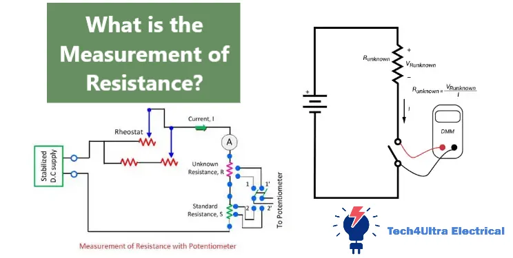
What is the measurement of resistance?
The measurement of resistance refers to determining how much a material or component resists the flow of electric current. It’s expressed in ohms (Ω) and helps identify issues like damaged components or poor connections in circuits. Tools like a multimeter or ohmmeter are commonly used for this purpose.
What are the three methods of measuring resistance?
The three most common methods are:
- Two-terminal method: Simple and widely used for general-purpose testing.
- Four-terminal (Kelvin) method: Used for precision resistance measurement in low-resistance scenarios.
- Bridge method (like Wheatstone or Kelvin bridges): Ideal for lab-grade and highly accurate applications.
What is used to measure resistance?
Resistance is typically measured using tools like:
- Multimeter: Versatile device for voltage, current, and resistance.
- Ohmmeter: Specialized tool for just resistance measurement.
- Ductor or ESR meters: For low resistance and capacitive component testing.
What is the classification of resistance?
Resistance can be classified by its behavior and material type:
- Fixed resistors: Maintain a constant value.
- Variable resistors (potentiometers): Adjustable for tuning circuits.
- Thermistors: Temperature-dependent resistors.
- Photoresistors: Change resistance based on light exposure.
Each type plays a unique role in controlling current within electronic systems.