Contents
Have you ever noticed that your electronic system isn’t performing at its best—even though all components seem perfectly functional? The issue often lies in something simple but frequently overlooked: impedance matching. Ignoring this crucial factor can lead to signal loss, distortion, or poor power transfer. In this article on the Tech4Ultra Electrical website, you’ll learn what impedance matching really means, its practical applications, how to design an effective impedance matching circuit, and how to apply the correct impedance matching formula. Step by step, we’ll show you how to boost the performance of any electronic or RF system by mastering this essential technique.
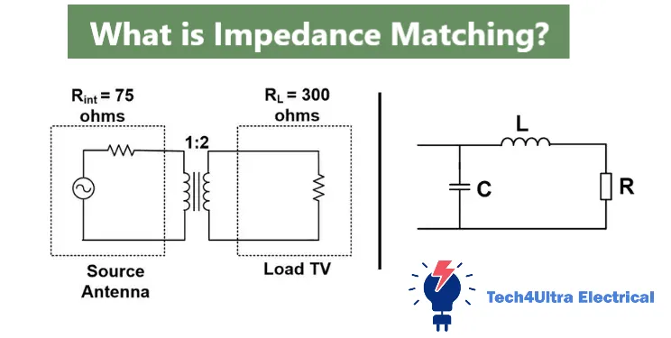
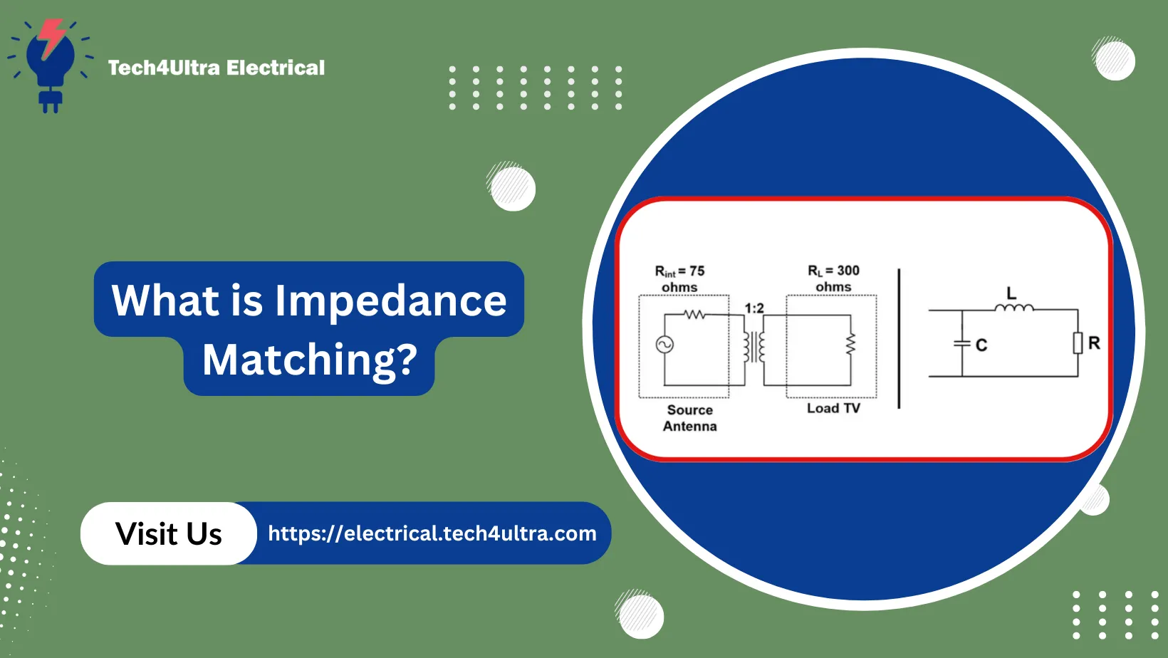
What is Impedance Matching?
Impedance matching is the process of making the output impedance of a source equal to the input impedance of the load to maximize power transfer and minimize signal reflection. This principle is critical in RF systems, audio electronics, and transmission lines, where mismatched impedances can lead to significant signal degradation.
Think of it like connecting a water pipe to a hose. If the pipe is too wide and the hose too narrow, water splashes and pressure drops. But when both sizes align perfectly, flow is smooth and efficient. In the same way, impedance matching ensures electrical signals flow cleanly from one device to another without loss.
One common misconception is that impedance matching is only important for high-frequency circuits. In reality, it’s also crucial in audio systems and low-frequency power transfer, especially where signal integrity matters. Another myth is that the goal is always to make impedances equal. In some cases, like noise reduction or signal conditioning, intentional mismatches are useful.
Mastering the concept of impedance matching helps in designing more efficient systems, whether you’re building antennas, amplifiers, or complex impedance matching circuits.
Read Also: Thermoelectric Generators Explained: How the Seebeck Effect Powers Clean Energy
Why Impedance Matching Matters
When it comes to designing efficient electronic systems, impedance matching isn’t just a technical detail—it’s a deal breaker. One of the biggest reasons it matters is power transfer efficiency. Without proper impedance matching, much of your signal’s power can bounce back toward the source instead of reaching the load. This leads to wasted energy and reduced system performance.
Beyond power, signal quality is also at stake. Poor impedance matching can introduce reflections and echoes, especially in high-frequency circuits like antennas or digital communication lines. These reflections distort the signal, raise the noise floor, and create errors in data transmission. Matching the impedance helps keep signals clean and stable, improving overall noise immunity.
Device compatibility is another overlooked benefit. Different components—like sensors, amplifiers, or transmission lines—often have specific impedance ratings. If these aren’t aligned using an impedance matching circuit, you might end up with unexpected behavior, such as low output levels or overheating components. Proper matching ensures devices work together as intended.
Whether you’re optimizing power flow, improving signal integrity, or ensuring system harmony, impedance matching is the key to making your electronics play nice.
Understanding Input, Output, Load, and Source Impedance
To really grasp impedance matching, you need to understand four terms that come up constantly: input impedance, output impedance, load impedance, and source impedance. They’re similar but not the same—and knowing the difference can save you a lot of headaches.
Input impedance is the impedance “seen” by a signal entering a device. Output impedance is what a device “offers” when delivering a signal. Source impedance is the internal resistance or impedance of the signal-generating device. Load impedance is the impedance of the component that receives the signal.
So how do they affect your circuit? Imagine connecting an audio player (source) to a speaker (load). If the output impedance of the player and the input impedance of the speaker aren’t properly matched, you’ll either get a weak signal or introduce distortion. A good impedance matching circuit ensures that power flows efficiently and the sound remains crisp.
In RF systems, impedance matching between a 50-ohm antenna and a 50-ohm transmission line is vital. Even slight mismatches can cause signal reflections, reducing range and reliability. In amplifiers, if the source impedance is too high compared to the input impedance of the amplifier, voltage gain is compromised.
These aren’t just textbook concepts—they’re everyday concerns in real electronics. Recognizing these impedance types helps you use the correct impedance matching formula and design circuits that work flawlessly.
Theoretical Basis: Maximum Power Transfer Theorem
The core theory behind impedance matching is the Maximum Power Transfer Theorem. It states that maximum power is delivered from a source to a load when the load impedance equals the complex conjugate of the source impedance. In purely resistive circuits, this simply means: load resistance = source resistance.
Let’s break it down with a basic derivation. Suppose you have a voltage source with internal resistance Rs, and it’s connected to a load RL. The power delivered to the load is:
P = V² × RL / (Rs + RL)²
To find the value of RL that maximizes power, take the derivative of P with respect to RL, set it to zero, and solve. You’ll find the maximum occurs when:
RL = Rs
So what does this mean for impedance matching? In practical terms, if your amplifier has an output impedance of 50Ω, your load (like a speaker or antenna) should also be 50Ω to get the most power transfer. Mismatched values lead to losses, heat, or weak signals.
This theorem is the foundation for designing any impedance matching circuit—it’s not just a rule, it’s a formula that underpins high-efficiency design across all electronics.
Impedance Matching Formulas and Calculations
At the heart of every impedance matching task lies a formula—simple yet powerful. For resistive circuits, the condition is straightforward: match the load impedance to the source impedance. But real-world electronics often involve reactive components like inductors and capacitors. That’s where the full impedance matching formula shines.
The general condition for maximum power transfer in AC circuits is:
ZL = ZS*
Here, ZL is the load impedance and ZS is the source impedance. The asterisk indicates the complex conjugate. So if ZS = 50 + j25 Ω, then ZL should be 50 - j25 Ω.
Example: Suppose your source impedance is 75 + j30 Ω. To match it, your load must be 75 - j30 Ω. If your actual load is purely resistive, say 75 Ω, then you need to add a reactive component like a capacitor or inductor to cancel out the reactive part.
To calculate those matching components, use basic formulas:
- Inductive reactance:
XL = 2πfL - Capacitive reactance:
XC = 1 / (2πfC)
Say your frequency is 1 MHz and you need to cancel +j30 Ω. You can add a capacitor with:
C = 1 / (2π × 1×10⁶ × 30) ≈ 5.3 nF
Understanding these formulas allows you to create a custom impedance matching circuit using just passive components. Whether it’s a Pi-network, L-section, or transformer-based method, it all starts with calculating what you need to match—and solving for it.
Watch Also: What Is an Electrical Grid System? Structure, Components, and Advantages Explained
Common Impedance Matching Techniques
There’s no one-size-fits-all impedance matching method. Engineers use different techniques depending on the frequency, load conditions, and complexity of the system. Here are the most common and effective approaches you’ll run into.
LC Networks: Pi, T, and L
These are the classic tools of the trade. LC networks use combinations of inductors and capacitors to cancel reactive components and transform resistance. An L-network is the simplest—great for matching a high impedance to a low one. A Pi-network is often used in RF transmitters for wider bandwidth and harmonic suppression. The T-network offers flexibility when neither source nor load impedance is known precisely.
- L-network: Uses one series and one shunt reactive component.
- Pi-network: Two capacitors and an inductor—ideal for tube amplifiers and RF output stages.
- T-network: Two inductors and a capacitor—useful in RF filters and broadband matching.
Transformer-Based Matching
This technique uses a step-up or step-down transformer to convert impedance levels. It’s perfect for audio circuits, power electronics, and RF baluns. Use the formula:
Turns ratio = √(ZL / ZS)
For instance, to match 50Ω to 200Ω, you need a turns ratio of 1:2.
Stub Matching (for RF)
Used in high-frequency systems, this involves attaching a short transmission line (open or shorted) at a specific point. By adjusting the length and position of the stub, you can cancel reactive components and fine-tune matching. Common in antenna feeds and waveguide systems.
Resistive Matching (Simplified)
Sometimes, brute-force simplicity works. Adding resistors in series or parallel can help match impedances, especially in low-frequency circuits. It’s not power efficient, though, since resistors dissipate energy—but it’s quick, cheap, and easy to implement in audio and test circuits.
Each method serves a purpose, and knowing when to apply which one is a skill every engineer develops. Choose wisely based on your circuit’s needs and constraints.
Applications of Impedance Matching
While impedance matching might sound like a niche concern, it’s a game-changer in many real-world applications. Let’s look at where it really makes a difference.
Audio Systems
Ever plugged high-impedance headphones into a phone and wondered why the sound is so faint? That’s a classic impedance mismatch. Audio amplifiers and speakers must be paired correctly for optimal volume and clarity. A good impedance matching circuit ensures full power transfer without distortion or loss of frequency response.
Transmission Lines (Coaxial, Waveguides)
In RF and high-speed digital systems, even a slight mismatch on a coaxial cable or waveguide can cause signal reflections. This leads to standing waves and degraded performance. Matching the transmission line’s impedance to both the source and load is essential to avoid signal loss and interference—especially in TV broadcasting and internet infrastructure.
Antennas and Wireless Communication
Whether it’s Wi-Fi, GPS, or Bluetooth, antennas must be matched to the transmitter or receiver. A typical antenna has a 50Ω input impedance, and if your device doesn’t match that, you’ll lose range and signal strength. Proper impedance matching here isn’t just about power—it’s about making your signal reach farther, cleaner, and more reliably.
Impedance Matching in Microcontroller Circuits
Even at low frequencies, microcontrollers can suffer from impedance issues, especially when driving sensors, ADCs, or communication lines like UART or I²C. Mismatched impedances can distort waveforms or introduce noise. Using resistors or simple RC filters can help achieve basic impedance matching for better signal integrity and reduced power loss.
No matter the field—audio, RF, or embedded systems—impedance matching is the unsung hero behind cleaner signals and efficient designs.
Advanced Topics
Impedance Matching in PCB Layout
Even a perfectly designed impedance matching circuit can fail if the PCB layout is poor. Trace width, length, and spacing all affect characteristic impedance. At high frequencies, a mismatched microstrip or stripline trace can cause signal reflections. Controlled impedance routing is key—especially for RF paths, clock lines, and differential pairs.
Matching Across Wide Frequency Ranges (Broadband)
Typical matching networks are narrowband—they work best at a specific frequency. But what if your system operates across a wide spectrum? That’s where broadband matching comes in. It uses multi-stage LC filters or tapered transmission lines to keep impedance matching effective across a range of frequencies. This is critical in SDRs, wideband antennas, and audio interfaces.
Adaptive Matching Networks
What if the load impedance changes during operation? Adaptive matching networks solve this using tunable components like varactors or MEMS switches. These circuits adjust in real-time to maintain optimal matching, which is ideal for mobile RF devices, reconfigurable antennas, and dynamic sensor systems.
These advanced techniques take impedance matching from static theory to smart, real-world design—perfect for engineers ready to push the limits.
Common Problems and Troubleshooting Tips
Impedance matching issues often show up as weak signals, overheating components, distorted waveforms, or high power loss. In RF systems, a mismatch might result in low transmission range or dropped packets. In audio, it could mean dull sound or unbalanced output.
So how do you know if mismatch is the problem? Look for signs like:
- Power reflection or return loss
- Reduced signal strength or bandwidth
- Increased noise or oscillation
To identify and fix these issues, engineers use tools like a network analyzer to measure impedance across frequencies, or a VSWR meter (Voltage Standing Wave Ratio) to detect how much power is reflected. A VSWR higher than 1.5:1 usually signals a mismatch worth fixing.
Once diagnosed, apply the right impedance matching circuit: an LC network for reactive loads, a transformer for big resistance gaps, or a resistive pad for quick, low-efficiency fixes. Small tweaks—like changing a capacitor value or adjusting trace width—can restore performance quickly.
With the right approach and tools, even stubborn mismatches become manageable.
Conclusion
To sum up, impedance matching is more than just a design rule—it’s a performance booster for any electronic system. We explored how it ensures efficient power transfer, preserves signal integrity, and prevents energy loss. From basic impedance matching formulas to advanced broadband networks, every technique has its place.
Ignoring impedance issues can lead to frustrating failures—from low audio output to unreliable wireless links. Whether you’re working on RF transmitters, audio amplifiers, or microcontroller circuits, building a solid impedance matching circuit should be part of your design checklist.
Final tip: always measure before you guess. Use a network analyzer or VSWR meter if possible, and simulate matching networks before building. For engineers and hobbyists alike, mastering impedance matching is one of those “small details” that makes a massive difference.
FAQs
What are the applications of impedance matching?
Impedance matching is used in many fields: audio systems to ensure clean sound transfer, RF systems to reduce reflections in antennas and coaxial cables, and power electronics to optimize load delivery. It’s also essential in microcontroller circuits where signal clarity matters for sensors and ADCs.
How to impedance match a circuit?
Start by measuring your source and load impedance. Then use an appropriate impedance matching circuit—like an LC network, transformer, or resistive pad. You can calculate the required components using the impedance matching formula, and always test your design using simulation or a network analyzer.
What are the applications of impedance?
Impedance matters in AC systems, audio engineering, RF communications, and power transfer. It affects how current flows, how much power is delivered, and whether signals distort or reflect. Engineers use impedance to design filters, match devices, and ensure system stability.
How to solve impedance mismatch?
First, identify the mismatch using tools like a VSWR meter or network analyzer. Then choose the right method: use LC components to cancel reactance, transformers to step impedance up or down, or stub tuning for RF systems. Testing and adjustment are key to a perfect match.