Contents
I still remember the first time I tried to understand how digital devices actually work—I thought it was way too complicated to grasp. But everything started to make sense when I learned about Logic Gates, the building blocks of Digital Electronics. In this article on the Tech4Ultra Electrical website, you’ll discover how these gates control the behavior of Digital Circuits, all based on simple rules of Boolean Logic. Whether you’re just curious or planning to dive deeper into tech, this guide will simplify the essentials and show you how digital systems truly operate.
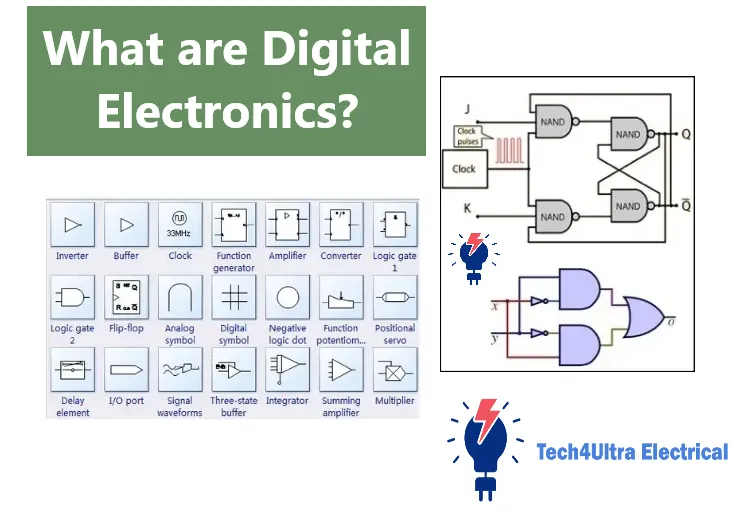
What is Digital Electronics?
I used to think that electronics was all about wires, resistors, and maybe the occasional spark. But that was before I got introduced to Digital Electronics. Suddenly, everything felt more structured, logical—even elegant.
Digital Electronics is the foundation of every modern device you use—your phone, laptop, even your microwave. Unlike analog systems that deal with continuous signals, digital systems work with just two states: on and off. Think of it as a world built entirely on 0s and 1s. Sounds simple, right? That’s because it is… at first.
What makes Digital Circuits so powerful is their precision and reliability. Since they’re based on binary logic, they’re less prone to signal degradation. In fact, their design is deeply rooted in Boolean Logic—a math system invented in the 1800s that uses logic operations like AND, OR, and NOT to make decisions.
And here’s the best part: everything in Digital Electronics boils down to tiny building blocks called Logic Gates. These gates form circuits that control everything from how your phone unlocks to how a rocket navigates space.
- Logic Gates are the smallest units of decision-making in electronics.
- Boolean Logic defines the rules that these gates follow.
- Digital Circuits combine gates to perform complex operations.
At first, I was overwhelmed by terms like flip-flops and multiplexers. But once I started building simple circuits using basic gates, it all clicked. That’s when I realized: you don’t need to be an engineer to appreciate how powerful and clean Digital Electronics really is.
So if you’ve ever wondered how your gadgets make decisions in a blink—this is where it all begins.
Read Also: Arduino vs Raspberry Pi: Which One Should You Use?
Digital vs. Analog Electronics
I used to confuse Digital Electronics with analog circuits all the time. They both power the gadgets we use—but they speak completely different languages. It wasn’t until I tried building a sound amplifier (analog) and then a simple counter circuit (digital) that the differences hit me hard.
Analog Electronics deals with continuous signals. Think of a dimmer switch—you can smoothly adjust brightness at any level. In contrast, Digital Electronics is like a regular light switch: it’s either on or off, 1 or 0. That makes digital systems easier to predict, but analog has its own strengths too.
| Aspect | Analog Electronics | Digital Electronics |
|---|---|---|
| Signal Type | Continuous | Discrete (0s and 1s) |
| Accuracy | Prone to noise and distortion | Highly accurate and noise-resistant |
| Complexity | Simple hardware, complex behavior | More components, but predictable |
| Use Cases | Audio, radio, analog meters | Computers, digital clocks, microcontrollers |
Pros and Cons
Analog Electronics
- Pros: Smooth signal control, better for real-time sensing like sound and light.
- Cons: Susceptible to interference, harder to store and reproduce signals.
Digital Electronics
- Pros: Reliable, easier to process, compress, and store. Foundation for Digital Circuits and Logic Gates.
- Cons: Needs more precise hardware, conversion from analog can reduce signal fidelity.
Understanding this comparison helped me choose the right components for my DIY projects. It’s not about which is better—it’s about choosing the right tool for the job.
Binary System and Digital Signals
I remember staring at a breadboard wondering why my LED only turned on or off—never in between. That’s when I learned about the Binary System and its magic in Digital Electronics.
Everything in Digital Circuits runs on binary: just 0s and 1s. These values represent two voltage levels—usually 0V for 0, and 5V for 1. This simple concept is called Boolean Logic, and it’s what powers Logic Gates that make decisions like “if this is true, then do that.”
Unlike Analog Electronics, which deals with signals that vary smoothly over time, digital signals are discrete. They jump sharply between two values. This gives digital systems their strength: they’re more immune to noise, easier to troubleshoot, and perfect for storing information.
Signal Characteristics
- Digital Signals: Discrete values (on/off), easy to replicate, low error rate.
- Analog Signals: Continuous variation, more detailed, but vulnerable to interference.
The first time I read a binary clock, it felt like decoding alien math. But once I cracked the pattern, I realized how elegant this system is. With just two digits—0 and 1—you can run the entire digital world.
Logic Gates and Boolean Algebra
The moment I wired my first AND gate and saw the LED light up only when both switches were pressed—it felt like magic. But that magic had a name: Boolean Logic. It’s the math behind how decisions are made in Digital Circuits, and Logic Gates are the components that execute those decisions.
There are seven basic types of Logic Gates, and each one operates according to a specific rule from Boolean Algebra:
- AND Gate: Outputs 1 only if all inputs are 1.
- OR Gate: Outputs 1 if at least one input is 1.
- NOT Gate: Inverts the input (0 becomes 1, and vice versa).
- NAND Gate: The opposite of AND.
- NOR Gate: The opposite of OR.
- XOR Gate: Outputs 1 only if inputs are different.
- XNOR Gate: Outputs 1 only if inputs are the same.
Truth Tables and Symbols
Truth tables changed everything for me. They made it easy to visualize how a gate behaves with different input combinations. For example, here’s a truth table for the AND Gate:
| Input A | Input B | Output (A AND B) |
|---|---|---|
| 0 | 0 | 0 |
| 0 | 1 | 0 |
| 1 | 0 | 0 |
| 1 | 1 | 1 |
Each gate has its own symbol—AND uses a flat-tipped D-shape, OR has a curved front, NOT is a triangle with a small circle at the output. Recognizing these on circuit diagrams is a must for anyone working with Digital Electronics.
Boolean Expressions and Simplification
Every gate and combination of gates can be written as a Boolean Expression. For example: Y = A · B represents an AND gate. As circuits get complex, we use Boolean rules to simplify them—like how A + A = A or A · 1 = A. Simplifying expressions can reduce gate count, save space, and improve circuit speed.
Back when I built my first full-adder circuit, I didn’t simplify anything—big mistake. It worked, but used way too many gates. A few Boolean tweaks later, I cut the gate count in half. Lesson learned: mastering Boolean simplification is just as important as understanding the gates themselves.
Digital Logic Families Explained
I’ll admit it—when I first heard terms like CMOS and TTL, I thought they were different brands of cereal. But these are actually families of Digital Circuits, and choosing the right one can make or break your project.
Each logic family is a group of electronic components built with specific technologies, each offering different balances of power consumption, speed, and compatibility. Here’s a quick breakdown:
- RTL (Resistor-Transistor Logic): The oldest family. Simple, but slow and power-hungry. Mostly obsolete now.
- DTL (Diode-Transistor Logic): Improved upon RTL by adding diodes, but still too slow for modern systems.
- TTL (Transistor-Transistor Logic): A major breakthrough. Faster, reliable, and widely used for many years in commercial Digital Electronics.
- CMOS (Complementary Metal-Oxide Semiconductor): My go-to for modern projects. Super low power consumption, high noise immunity, and excellent for battery-powered designs.
- ECL (Emitter-Coupled Logic): The speed champion. Used in high-frequency systems like radar and telecom, but consumes a lot of power.
Power, Speed, and Compatibility Trade-offs
Choosing the right family depends on your needs:
- Need speed? Go with ECL.
- Low power? CMOS is king.
- Easy to interface with microcontrollers? Stick with TTL.
Once, I used TTL chips in a low-power design—bad move. My battery didn’t last a day. Switching to CMOS solved it. The lesson? Understand your logic family before wiring your circuit, because every choice has a trade-off in power, speed, and compatibility.
Combinational Logic Circuits
My first experience with Combinational Logic Circuits was a simple calculator project using LEDs. I wanted it to add two binary numbers—turns out, that meant building something called a Half Adder. Once I got it working, I felt like I’d cracked the code of Digital Electronics.
Combinational logic circuits are systems where the output depends only on the current inputs—not on previous states. That’s a big contrast to sequential circuits, which we’ll talk about later. These circuits rely heavily on Logic Gates and follow strict rules defined by Boolean Logic.
Key Components
- Adders: These circuits perform binary addition. A Half Adder handles two inputs, while a Full Adder includes carry-in for chained operations like multi-bit addition in processors.
- Subtractors: Similar to adders but perform binary subtraction. Often built using inverters and adders combined with control logic.
- Multiplexers (MUX): Think of them as digital selectors. They choose one of many inputs and route it to a single output based on control signals. Super useful in data routing.
Real-World Use Cases
Once I built a 4-to-1 multiplexer to switch between sensor inputs on a weather monitoring device. It saved me from wiring multiple analog-to-digital converters and streamlined the entire circuit.
- Adders: Used in ALUs (Arithmetic Logic Units) inside CPUs and microcontrollers.
- Subtractors: Found in digital counters, timers, and signal processing units.
- Multiplexers: Key in memory addressing, signal routing, and even digital audio mixers.
The beauty of Combinational Logic is in its simplicity. You don’t need memory or clocks—just inputs, gates, and clean outputs. And once you master the basics, building things like binary calculators or selection systems becomes surprisingly intuitive.
So if you’re diving into Digital Circuits, combinational logic is where your creativity starts to come alive.
Sequential Logic Circuits
I still remember the first time I built a binary counter using Flip-Flops. Watching those LEDs blink in perfect sequence felt like I had discovered time control in Digital Electronics. That’s when I realized: Sequential Logic Circuits are where things start to get truly dynamic.
Unlike Combinational Logic Circuits that rely only on current inputs, sequential circuits use memory elements to track past states. Their behavior depends on both current inputs and the history of those inputs, thanks to storage devices like flip-flops.
Flip-Flops
Flip-Flops are the building blocks of memory in Digital Circuits. Each type has its own use case:
- SR Flip-Flop: The simplest type. Set (S) and Reset (R) control the output. But if both are active, it creates an undefined state—tricky for beginners.
- D Flip-Flop: Stands for “Data” or “Delay.” Captures the input only on the clock edge—great for timing-sensitive operations.
- JK Flip-Flop: A universal flip-flop. It avoids the SR’s invalid state and can toggle outputs.
- T Flip-Flop: Short for “Toggle.” Useful for counters—each clock pulse flips the output.
Counters and Shift Registers
My favorite project using sequential logic was a 4-bit binary counter. It looked like a light show, but each blink was a precise count, powered by T flip-flops.
- Counters: Use flip-flops to count events, time intervals, or cycles. They’re core to clocks, timers, and processors.
- Shift Registers: Move bits left or right across flip-flops. Used in data serialization, digital displays, and even old-school game controllers.
Clock and Timing Concepts
Everything in sequential circuits revolves around the clock signal—a continuous pulse that tells flip-flops when to update. Without a stable clock, your circuit could glitch or lose sync. Think of the clock as a metronome keeping your digital band in rhythm.
I once forgot to debounce a clock signal from a push button—and my counter went wild. That tiny mistake taught me how crucial clean timing is in Boolean Logic systems.
In short, sequential logic brings memory, order, and control to digital design. If combinational logic is the brain, sequential logic is the heart that keeps everything beating in time.
Register Transfer Level Design
The first time I heard “Register Transfer Level” (or RTL), I thought it was some kind of elite programming language. Turns out, it’s not a language—it’s a design philosophy, and one that helped me finally connect the dots between theory and real Digital Circuits.
RTL is all about describing how data moves between registers and how logic controls that flow. Registers are storage units made of flip-flops, and the “transfer” part is managed using Boolean Logic and Logic Gates. What makes RTL powerful is that it abstracts the hardware into a series of clocked operations—perfect for creating structured, modular designs.
RTL Basics
- Registers: Store binary data, typically updated on a clock edge.
- Combinational Logic: Determines what data goes where.
- Control Logic: Uses signals to enable or disable data transfers.
State Machine Example
One of my first RTL projects was designing a traffic light controller using a finite state machine (FSM). I defined three states—Green, Yellow, Red—and used D flip-flops to track which state was active. Transitions were based on a clock signal and timed logic.
Each state had specific outputs (lights ON/OFF) and defined when to switch to the next. It was like creating a digital storybook, where each page depended on the last and triggered the next.
Once I visualized it using RTL diagrams, debugging became way easier. That moment marked my shift from wiring random gates to designing with purpose.
Circuit Design and Minimization Techniques
I’ll be honest—when I started designing Digital Circuits, they were messy. Too many Logic Gates, unnecessary connections, and let’s not talk about the power consumption. That’s when I discovered circuit minimization techniques, and everything changed.
Minimization is all about reducing the complexity of Boolean Logic expressions while keeping the same output. Fewer gates mean faster, cheaper, and more efficient circuits. There are two methods that saved my projects more times than I can count: Karnaugh Maps and the Quine-McCluskey algorithm.
Karnaugh Maps (K-Maps)
K-Maps are a visual method of simplifying Boolean expressions. You place 1s in a grid based on the truth table, then group adjacent 1s in powers of two. It’s like solving a puzzle—but with logic.
- Best for 2–4 variables.
- Quick and intuitive.
- Shows redundant terms clearly.
Once, I used a K-Map to reduce a 6-gate circuit to just three gates. My breadboard finally had room for wires again.
Quine-McCluskey Algorithm
If K-Maps are too limited for larger circuits, this tabular method does the trick. It compares binary terms, finds prime implicants, and eliminates redundancies step by step.
- Works well for more than 4 variables.
- Can be programmed for automation.
- Accurate, but more time-consuming manually.
Logic Optimization Tips
- Always simplify before building.
- Use common sub-expressions to reduce repeated logic.
- Test with truth tables after optimization.
Learning minimization wasn’t just a time-saver—it was a sanity-saver. Now I look at every Digital Electronics problem and think: how can I make this smarter, not harder?
Key Design Considerations
When I first started designing Digital Circuits, I thought getting the logic right was enough. It wasn’t. My circuit worked… sometimes. Other times, it glitched, lagged, or just froze. That’s when I learned that logic is only part of the picture—timing and signal behavior matter just as much.
Timing Analysis
Every Digital Electronics system is driven by timing. Whether it’s clock signals in sequential circuits or propagation delays in combinational logic, you need to analyze how long it takes signals to travel through gates. Miss this, and your circuit could update too soon—or too late.
- Setup Time: Minimum time a signal must be stable before the clock edge.
- Hold Time: How long it must stay stable after the clock edge.
Glitches and Fan-Out
I once wired multiple gates to a single output without thinking—classic mistake. That’s when I ran into a fan-out problem: the output couldn’t drive all those inputs. Signals weakened, and glitches appeared.
- Glitches: Tiny, unwanted pulses caused by differences in gate delay.
- Fan-Out: The maximum number of gate inputs an output can drive without degradation.
Signal Integrity and Metastability
Metastability was the weirdest concept I had to accept. It’s when a flip-flop gets stuck between states—neither 0 nor 1—often because of async inputs or timing violations. It’s rare but dangerous in critical systems.
To fix this:
- Use synchronizer circuits for asynchronous inputs.
- Keep wire lengths short and minimize capacitance.
- Use buffers when driving multiple gates or long traces.
These design rules might seem small, but they’ve saved me from hours of debugging and unexpected failures. Digital design isn’t just about what you build—it’s also about how you make it reliable.
Tools for Digital Design
The first time I heard about VHDL and Verilog, I thought they were programming languages for spacecraft. But once I got my hands on them, I realized they’re the core of modern Digital Electronics development—and way more accessible than I expected.
EDA Tools: VHDL, Verilog & Simulation
EDA (Electronic Design Automation) tools are the backbone of professional circuit design. Instead of building with physical Logic Gates, you describe your system using hardware description languages like:
- VHDL: Verbose but very structured. Great for large projects in aerospace and defense.
- Verilog: More concise and commonly used in commercial electronics and FPGA development.
Once your design is ready, you use simulation tools (like ModelSim or Vivado) to test it before ever touching a soldering iron. That’s where I caught my first timing bug—without burning out a single chip!
FPGA Environments & Logic Analyzers
- FPGA Design Tools: Platforms like Xilinx Vivado and Intel Quartus let you implement digital systems on FPGAs—reconfigurable chips that mimic any Digital Circuit you can describe.
- Logic Analyzers: These devices capture and visualize digital signals in real-time, helping you debug everything from signal timing to glitches.
These tools might seem intimidating at first, but once you get hands-on, they open up a whole new level of precision and control. They transformed how I approach circuit design—from guesswork to confidently structured development using Boolean Logic and real-world timing data.
Applications of Digital Electronics
I remember the moment I realized how deeply Digital Electronics impacts our lives. I was fixing a broken remote control when it hit me—this tiny gadget uses Logic Gates, Boolean Logic, and microcontrollers to send commands wirelessly. That same logic powers almost everything we use today.
Consumer Electronics
From smartphones to smartwatches, every modern gadget is built on the back of Digital Circuits. Inside your TV, game console, or even microwave, there are processors, memory units, and sensors working together—processing inputs, making decisions, and controlling outputs in real time.
- Smartphones: Signal processing, touch response, UI control.
- Wearables: Data logging, wireless communication, health tracking.
- Home Appliances: Temperature control, timers, safety checks.
Communication Systems
Digital Electronics revolutionized how we communicate. From fiber optics to satellite links, everything relies on binary data transmission. Modems, routers, and mobile base stations are built using complex Digital Circuits that encode, decode, and route information across the globe.
- Signal modulation and demodulation.
- Error detection and correction using logic systems.
- Data encryption for secure communication.
Automotive and Industrial Automation
When I installed a reverse parking sensor in my old car, I got a firsthand look at how vehicles use Digital Logic. Modern vehicles are full of microcontrollers managing everything from engine performance to brake systems.
- ECUs (Electronic Control Units) using sensors and digital logic.
- Automated assembly lines powered by programmable logic controllers (PLCs).
- Safety systems using real-time digital feedback.
Whether it’s your coffee machine or a factory robot, Digital Electronics is the silent intelligence making everything smarter, faster, and more reliable.
Future Trends in Digital Electronics
If you think Digital Electronics has peaked, think again. The future is already knocking—with technologies that once felt like science fiction now being prototyped in labs and tested in real devices. Let me share a few trends that blew my mind the first time I read about them.
Quantum Logic & Memristors
Quantum Logic breaks the binary barrier. Instead of just 0s and 1s, quantum bits (qubits) can exist in multiple states at once, thanks to superposition. This opens the door to radically faster processing, especially for complex problems like encryption or molecule simulation.
Memristors are another game-changer. These components “remember” how much current passed through them, making them perfect for low-power memory and brain-like computation. They blur the line between memory and processing, allowing for more efficient Digital Circuits.
Optical & Neuromorphic Computing
Optical computing replaces electrons with photons—light-speed processing with minimal heat. This tech promises insane bandwidth and speed, which could revolutionize how we build processors and communication systems.
Neuromorphic computing mimics the human brain using Boolean Logic inspired by neurons and synapses. Chips like Intel’s Loihi already emulate brain-like functions for tasks like pattern recognition and sensory processing—with far less energy than traditional CPUs.
The future of Digital Electronics is fast, intelligent, and maybe even a little weird. But one thing’s for sure—it’s not slowing down anytime soon.
Conclusion
From blinking LEDs to powerful microprocessors, Digital Electronics forms the backbone of our modern world. Throughout this guide, we’ve explored everything from basic Logic Gates and Boolean Logic to complex Digital Circuits and the exciting frontiers of quantum and neuromorphic computing.
What starts as a simple binary 0 or 1 can grow into systems that run cars, power communication networks, and simulate brain-like intelligence. Whether you’re a student, hobbyist, or future engineer, understanding digital design gives you the tools to build, innovate, and troubleshoot with confidence.
As technology evolves, so does our relationship with it. The more we understand the logic behind the scenes, the better equipped we are to shape the future—not just consume it. The digital world isn’t just happening to us—we’re designing it, one gate at a time.
FAQs
What is the simple definition of digital electronics?
Digital Electronics is a branch of electronics that deals with circuits operating on digital signals—specifically binary values: 0 and 1. These signals represent OFF and ON states and are used to build logic-based systems using Logic Gates and Boolean Logic.
What are examples of digital electronics?
Common examples include computers, smartphones, digital clocks, calculators, microcontrollers, and gaming consoles. These devices rely on Digital Circuits to process information, store data, and make decisions based on logic operations.
What are the applications of digital circuits?
Digital Circuits are used in almost every modern electronic device. They power consumer electronics, control automotive systems, manage industrial automation, process signals in communication systems, and are at the core of medical equipment, security systems, and robotics.
What do we study in digital electronics?
In a digital electronics course, you typically study Logic Gates, Boolean Algebra, Combinational and Sequential Circuits, flip-flops, counters, registers, and Digital Design tools like VHDL or Verilog. It’s about understanding how logic and hardware combine to create smart electronic systems.
2 thoughts on “SCR turn-on time Explained: Complete Guide to Switching and Turn‑Off Characteristics”