Contents
Have you ever wondered why some generators suddenly fail or catch fire without warning? The truth is, many of these incidents happen due to the lack of a simple yet critical system: differential protection. In this article on the Tech4Ultra Electrical website, you’ll discover how generator differential protection works and why it’s essential for safeguarding any alternator or electrical generator. By the end, you’ll know exactly how to prevent major losses with one smart protection strategy.
What Is Differential Protection?
Basic Concept and Historical Context
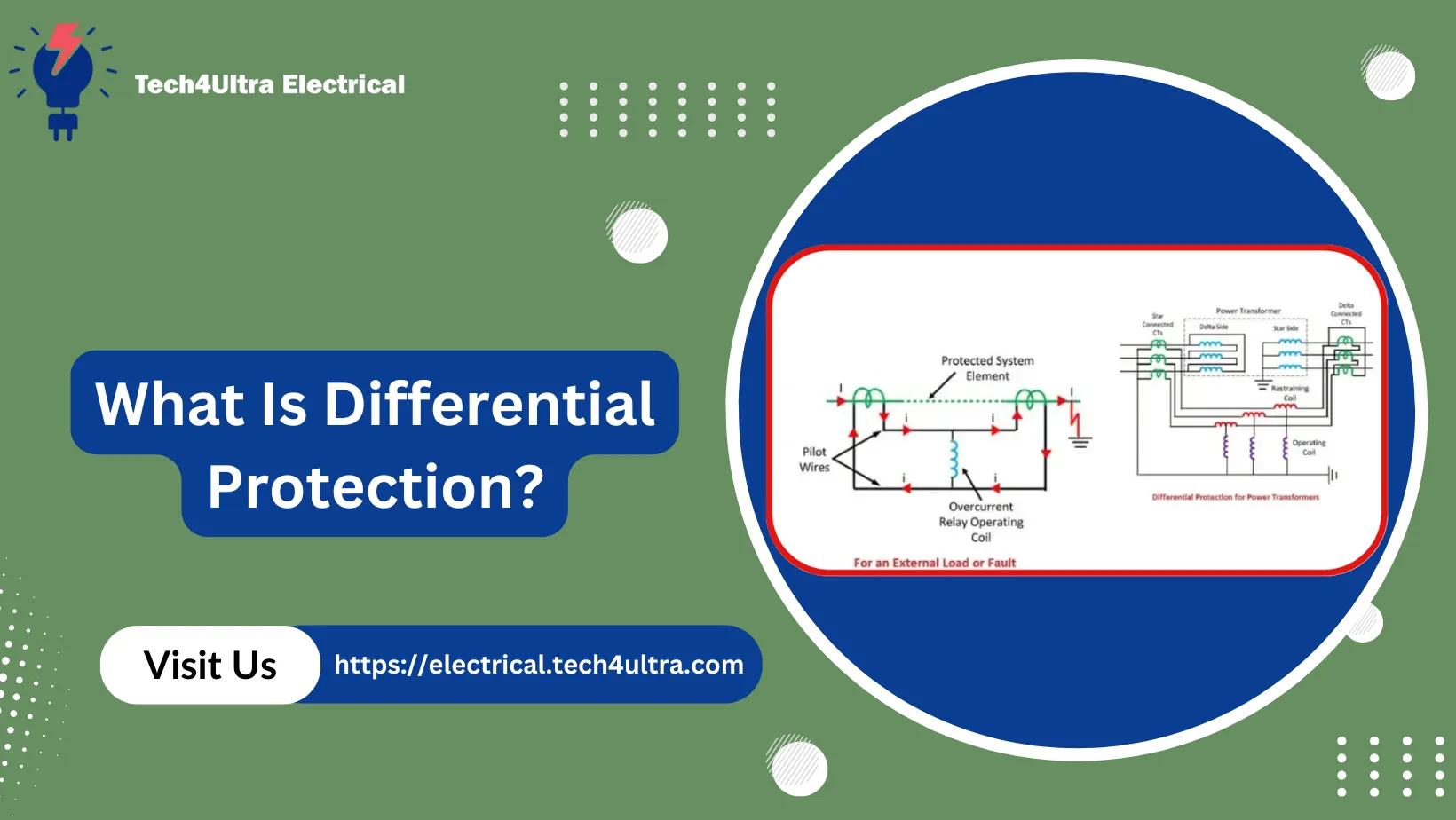
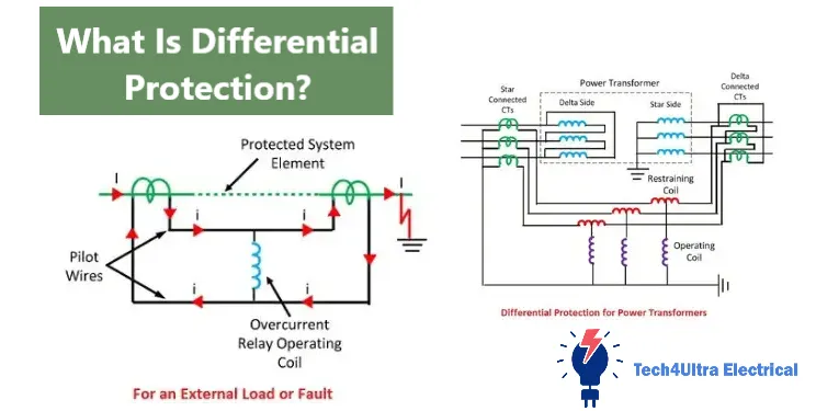
When I first started working in electrical protection systems, differential protection sounded like a fancy term reserved for high-voltage substations. But it’s not just about complexity — it’s about precision. At its core, differential protection is a method that compares the current entering and leaving a protected zone. If there’s any mismatch beyond a set threshold, it assumes a fault exists within that zone.
This concept traces back over a century, pioneered by Charles H. Merz and Bernard Price in the early 1900s. Back then, it was revolutionary. While other protection methods responded to the “amount” of current, differential protection responded to the “difference” in current. That nuance made all the difference — literally.
Comparison with Other Protection Methods
So, how is differential protection different from overcurrent or earth fault protection? Let me tell you from experience — overcurrent protection is like a smoke alarm; it reacts when things go way out of control. But differential protection? It’s more like a security camera that spots something fishy before the place goes up in flames.
Here’s a quick comparison:
- Overcurrent protection: Trips when current exceeds a set limit. Effective for external faults or major internal ones, but not precise for localized damage.
- Earth fault protection: Detects leakage to ground. Important, but again — not location-specific and may miss phase-to-phase issues.
- Differential protection: Targets internal faults only. If the current in ≠ current out, the system knows something’s wrong inside the equipment — fast and accurate.
In a nutshell, differential protection is surgical — it reacts only when needed and ignores everything else. That’s a huge deal in complex networks.
Relevance to High-Value Assets Like Generators
Now, let’s talk real-world impact. Imagine a multi-million-dollar generator or alternator running without adequate generator differential protection. A simple winding short could go undetected until catastrophic failure hits. I’ve seen it happen. It’s not pretty — downtime, repairs, lost revenue.
High-value equipment like generators deserves more than basic protection. That’s why alternator differential protection is considered essential. It provides fast, selective, and reliable protection where it matters most — right at the heart of your power system.
Because when your asset costs seven figures, you don’t want to rely on a $50 protection relay.
Read Also: Motor Protection Guide: Types, Devices, Faults & NEC Selection Tips
Working Principle of Differential Protection
Vector Summation of Currents
The core idea behind differential protection is simple but powerful: if everything is working correctly, the current entering a protected zone should equal the current leaving it. That means the vector sum of currents should be zero. This is the principle of differential current calculation.
Mathematically, it’s expressed as: Iin – Iout = 0 (ideal case). But when a fault occurs within the zone, this balance is lost. The difference, called the residual current, becomes the trigger for the protection system to act.
In real-world scenarios, small mismatches can happen even under normal operation due to CT errors or transformer inrush currents. So, a setting threshold is defined to prevent unnecessary tripping.
Role of CTs in Protection
Current Transformers (CTs) are the unsung heroes in any generator differential protection setup. They’re placed at both ends of the protected equipment — like an alternator — and are responsible for measuring the current flowing in and out.
Their accuracy is critical. If one CT is slightly off, the system might detect a false differential current. That’s why we often match CTs carefully in terms of ratio, burden, and phase response.
CTs convert the actual current into smaller, manageable signals that the relay can handle. The relay then continuously compares these signals to detect internal faults.
Ideal vs. Fault Conditions (Use Diagrams or Illustrative Scenarios)
Imagine a generator during normal operation. Current flows from the generator to the bus. The CT at the generator end sees 100A, and the CT at the bus end also sees 100A. The relay compares these and sees no difference — all is well.
Now imagine a turn-to-turn short circuit inside the generator winding. The generator end CT still sees 100A, but due to the fault, only 70A reaches the bus. That 30A difference — the differential current — tells the relay: “Hey, something’s wrong inside.” The relay trips the breaker to isolate the fault instantly.
Alternator differential protection relies on this principle to detect faults that would otherwise be invisible to overcurrent relays. It’s precise, localized, and fast — exactly what high-value systems need.
In short, if the currents don’t balance, the relay doesn’t ask questions. It just acts — and that’s what saves equipment from major damage.
Key Components and Circuit Layout
Line-Side and Neutral-Side CTs
In a typical generator differential protection system, two sets of Current Transformers (CTs) are used: one on the line side (output to the bus) and one on the neutral side (connected to the grounding system). This configuration ensures that the protection zone covers the entire alternator winding.
Why both sides? Because internal faults can occur at either end. Using CTs on both line and neutral sides allows the relay to detect any unbalanced current caused by internal faults. Without both, you risk leaving parts of the generator unprotected.
Protection Relay Architecture (Operating and Restraint Coils)
The protection relay used in differential protection consists mainly of two critical components: the operating coil and the restraint coil. The operating coil receives the differential current — the vector sum of the CT inputs. If this current exceeds a set threshold, the relay issues a trip signal.
The restraint coil, on the other hand, carries the average or sum of the CT currents. It acts like a stability check, ensuring that false operations caused by CT errors or transformer inrush don’t trigger a trip. This dual-coil system is the heart of the relay’s selectivity and dependability.
Stabilizing Resistor and Its Function
One often-overlooked yet vital component in the alternator differential protection circuit is the stabilizing resistor. This resistor is connected in series with the operating coil and helps control the voltage during high-current external faults.
Imagine a short circuit on the busbar, outside the generator. The current through the CTs might be enormous, but ideally balanced. However, slight mismatches could cause a false differential current and trip the relay unnecessarily. The stabilizing resistor prevents this by limiting the sensitivity during these high-current events.
It’s like a filter that says, “Let’s not overreact unless the imbalance is serious.”
Detailed Schematic Explanation
Let’s visualize the complete differential protection layout. On each end of the generator winding — line and neutral — we have matched CTs. The secondaries of these CTs are wired in opposition and connected to the relay.
Under normal conditions, the CT currents cancel each other out, and no current flows through the operating coil. But if an internal fault occurs, the imbalance causes current to flow through the operating coil, overcoming the restraint coil and tripping the breaker.
Add to that a stabilizing resistor in series with the operating coil and possibly a fast-acting relay with programmable logic. That’s a solid, reliable setup for generator differential protection</b
Types of Faults Detected
Internal Faults: Phase-to-Phase, Phase-to-Ground, Inter-Turn
One of the biggest advantages of differential protection is its ability to detect internal faults — the kind that can silently destroy a generator or alternator from the inside out. Let’s break down the types:
- Phase-to-phase faults: Occur when two phases inside the winding come into direct contact. These faults cause severe heating and must be cleared instantly. Generator differential protection identifies the imbalance in phase currents and trips quickly.
- Phase-to-ground faults: Happen when one phase touches ground. These are common in systems with high-resistance grounding. A slight leakage might not trigger overcurrent relays, but the differential relay catches the deviation in input/output current.
- Inter-turn faults: These are trickier — short circuits between adjacent turns of the same phase. They cause localized heating and are often missed by traditional protection schemes. But with sensitive differential protection, you can detect even these subtle internal issues.
Bottom line? If it’s inside the protection zone, the differential relay will catch it.
External Faults and Relay Behavior
External faults — like a short circuit on the busbar or feeder — can generate huge fault currents. But these should not trigger the alternator differential protection, because the fault is outside the protection zone.
This is where the magic of the relay’s design shines. Thanks to the restraint coil and proper CT matching, the currents on both ends of the generator remain nearly equal, so no differential current flows. The relay stays silent, as it should.
This selectivity is critical. Tripping on external faults would mean unnecessary generator shutdowns, which can cost thousands in lost generation.
Inrush Current and Differential Relay Performance
One thing that used to confuse me early in my career was why a transformer or generator would trip during energization — even though there’s no fault. The culprit? Inrush current.
Inrush current is a temporary surge that occurs when a generator is first connected to the system. It can create a false imbalance in CT readings. But advanced differential protection relays are designed with inrush detection algorithms, often based on second harmonic restraint. They detect the unique waveform of inrush and hold off tripping.
So while the current spikes, the relay thinks twice — preventing unnecessary trips and keeping your generator online.
Percentage Differential Relay Explained
What Is Percentage Biasing?
One thing you’ll quickly learn in the field is that not all differences in current are faults. That’s where the concept of percentage differential protection — also called percentage biasing — comes in. It’s a method that adjusts the sensitivity of the relay based on the magnitude of through current.
Here’s how it works: the relay doesn’t just look at the absolute difference between input and output currents. Instead, it compares the differential current to a percentage of the total current flowing through the generator or alternator. This prevents the relay from tripping when small mismatches happen due to CT saturation, measurement error, or inrush.
How It Helps Avoid Nuisance Tripping
Imagine your generator’s CTs are slightly mismatched. During high load or external faults, these differences could falsely appear as internal faults. Without biasing, your differential protection relay would trip — not good.
With percentage biasing, the relay becomes “smart.” It allows a higher tolerance for current mismatch during high-load or fault-current conditions. That means fewer false trips and higher system stability.
In practical terms, the relay won’t trip unless the differential current exceeds both an absolute minimum and a percentage of the total current. This two-layer check — also known as “restraint” — makes the relay more selective and robust.
Typical Biasing Curves and Settings
In a typical generator differential protection relay, the biasing is represented graphically as a curve. The X-axis shows the average of the two CT currents (restraint current), and the Y-axis shows the differential current (operating current).
The curve defines the threshold: below it, the relay doesn’t trip. Above it, the relay operates. A common setting might be:
- Below 30% load: fixed differential setting (e.g., 20% of rated current)
- Above 30% load: slope increases proportionally with load
This biasing technique ensures the alternator differential protection stays inactive during normal operation or external faults, but responds instantly to real internal issues — like winding shorts or phase faults.
That’s the kind of precision every high-value asset deserves.
Advanced Issues and Practical Challenges
CT Saturation and Mismatch
One of the most common headaches in differential protection schemes is CT saturation. During heavy faults or sudden load changes, one of the Current Transformers (CTs) might saturate — meaning it no longer accurately mirrors the actual current. This causes a mismatch between input and output signals.
For example, if the line-side CT saturates during an external fault, the relay might think there’s an internal issue and trip the generator. To avoid this, high-quality CTs with proper accuracy class and knee-point voltage must be used. It’s also important to match CT characteristics on both sides of the alternator to maintain balanced readings.
Handling Magnetizing Inrush Currents
When a generator is energized, it draws a temporary, non-fault current called magnetizing inrush. This current is rich in harmonics and can mimic fault-like behavior — especially from the relay’s perspective.
Advanced generator differential protection relays use harmonic restraint, particularly second harmonic filtering, to recognize inrush conditions. If the waveform contains a significant second harmonic component, the relay assumes it’s inrush and blocks the trip. This is crucial during cold startups or synchronization after maintenance.
Spill Current and Leakage Detection
Spill current is the unbalanced current that flows through the operating coil of the differential relay. In a healthy system, this should be zero or very small. But factors like CT mismatch, wiring errors, or core saturation can create artificial spill current — tricking the relay.
To tackle this, modern relays apply a low-set threshold and a percentage biasing mechanism, allowing small spill currents without action. But if the spill current persists or grows — especially during no-load — it could signal real leakage or a developing internal fault.
Time Delays and Stability Issues
Another practical challenge is balancing relay speed vs. system stability. Ideally, we want the differential protection to act instantly during faults. But premature or false tripping can destabilize the entire power network.
To counter this, time delays are sometimes introduced in low-sensitivity zones or during specific operations (like startup or switching). Adaptive relays even adjust delay settings in real-time based on system loading and harmonic content.
It’s a tradeoff — speed versus security — and the optimal configuration depends on the size of your generator, the value of your assets, and your network’s tolerance for downtime.
In high-stakes environments, a well-calibrated alternator differential protection relay can mean the difference between a safe trip and an expensive blackout.
Design Best Practices and Real-World Applications
How to Size and Place CTs
If you ask any experienced engineer what can ruin the best differential protection setup, the answer is easy: poorly sized or badly placed Current Transformers (CTs). The placement and sizing of CTs must be accurate to ensure a true reflection of the current flowing through the generator or alternator.
CTs should be installed as close as possible to the winding terminals on both the line and neutral sides. Use the same CT ratio and type on both sides to avoid imbalance. A common practice is to use 1 A or 5 A secondary CTs with a high accuracy class (typically 5P or 10P).
Always calculate the burden of the CT circuit — including wiring length and relay input impedance — and ensure the CT knee-point voltage comfortably exceeds the maximum fault current expected. This avoids CT saturation, especially during high-current external faults.
Generator Types and Relay Coordination
Not all generators behave the same. A diesel unit, a hydro machine, and a nuclear reactor turbine all have different dynamics. Your generator differential protection must be tuned accordingly.
- Thermal generators: Typically large, with significant fault current levels. Use high-sensitivity relays with fast tripping.
- Hydro generators: Often have longer winding leads; you must extend the protection zone accordingly and consider inrush sensitivity.
- Nuclear units: Require redundant and fail-safe protection logic. Often involve dual relays and supervision schemes.
Relay coordination must also ensure harmony with backup protections like overcurrent or distance protection. No one wants a race condition between relays during faults.
Use Cases in Thermal, Hydro, and Nuclear Plants
Differential protection is used in nearly every utility-grade power station. In hydro plants, it guards against stator winding shorts. In thermal plants, it responds to inter-turn and phase faults. In nuclear stations, it’s often part of a triple-redundant system to meet regulatory safety standards.
Whether the generator is 50 MW or 1000 MW, the same core principle applies: protect the winding zone with precise CT placement and a reliable relay.
Case Study: Fault Detection in a 500 MW Thermal Generator
In one incident, a 500 MW steam turbine generator experienced a sudden phase-to-phase fault due to insulation failure. The CTs on both line and neutral sides were perfectly matched, and the alternator differential protection relay detected a 150 A mismatch within milliseconds.
The relay tripped the main breaker instantly. Damage was contained to one section of the winding, and the unit was offline for only 36 hours. Without the relay, this could have meant a complete stator rewind and over a month of downtime.
That’s the power of good protection: when designed right, it saves not just equipment — but time, money, and reputations.
Watch Also: Electric Generator: How It Works, Types, and Complete Guide to Electromagnetic Induction
Comparison with Other Generator Protection Schemes
Differential vs. Overcurrent
Let’s start with the classic debate: differential protection versus overcurrent protection. Overcurrent is simple — if the current exceeds a set value, it trips. That’s great for detecting big faults, but what about subtle internal issues?
That’s where generator differential protection stands out. It doesn’t care how big the current is. It cares whether the input and output match. Even if a small inter-turn fault occurs with minimal current rise, differential protection will catch it.
Overcurrent can miss slow-developing faults or react late. On the flip side, it’s cheaper and easier to set up. Differential protection needs precise CT matching and careful calibration, but it’s worth it for critical assets like alternators.
Distance and Reverse Power Protection
Distance protection is commonly used in transmission systems. It measures the impedance between the relay and fault to estimate distance. While useful on long lines, it’s not ideal inside a generator. The impedance profile of a stator winding is complex and non-linear.
Reverse power protection, on the other hand, is designed to detect conditions where the generator starts drawing power instead of supplying it — typically a sign of prime mover failure. While it protects against motoring conditions, it doesn’t catch internal electrical faults.
In short: these schemes complement, but don’t replace, alternator differential protection.
Pros and Cons of Each Method
- Differential protection: Highly accurate for internal faults; fast operation; requires matched CTs and careful settings.
- Overcurrent protection: Simple and low-cost; may miss internal or low-magnitude faults; slower to act.
- Distance protection: Effective for long lines; less accurate within generator stator zones.
- Reverse power protection: Useful for mechanical faults; doesn’t address electrical internal issues.
At the end of the day, no single scheme is perfect. But for internal electrical faults in high-value machines, generator differential protection remains unmatched.
Conclusion
Recap of Differential Protection Principles
Throughout this guide, we’ve seen why differential protection is considered the gold standard for internal fault detection in generators and alternators. By comparing currents at both ends of the protected zone and reacting only to imbalances, it offers unmatched accuracy and speed.
From handling inter-turn faults to avoiding false trips through percentage biasing and harmonic restraint, generator differential protection is engineered for reliability — even in the most complex environments.
Importance in Digital and Smart Grid Systems
As electrical grids evolve, protection systems must evolve too. Modern differential protection relays are no longer isolated hardware devices; they’re part of broader digital ecosystems.
In smart grids, where data from multiple points flows into centralized systems, protection must be fast, communicative, and remotely configurable. Relays now support protocols like IEC 61850 and offer real-time diagnostics. They don’t just protect — they inform.
That’s why alternator differential protection is more relevant than ever. In a world where downtime equals dollars lost, its precise and selective operation is crucial.
Role of AI and Predictive Maintenance
Looking ahead, AI is beginning to reshape how we think about protection. Machine learning models can now analyze waveform patterns and historical data to predict potential failures before they occur.
Predictive maintenance tools are being integrated with differential protection systems to flag abnormal conditions that don’t yet qualify as faults — like insulation degradation or gradual CT drift.
The future isn’t just about reacting fast. It’s about knowing what’s coming — and that’s where AI meets protection. Expect generator differential protection to become not just a shield, but a strategic sensor in the digital energy landscape.
FAQs
What is the differential protection of an alternator?
Differential protection of an alternator is a method used to detect internal faults, such as short circuits between windings or phase-to-ground faults, by comparing the current entering and leaving the alternator. If there’s a mismatch, the relay trips to isolate the faulted machine quickly, minimizing damage and system disruption.
What is the differential protection of a generator transformer?
Differential protection of a generator transformer operates on the same principle: it measures and compares current at both ends of the transformer. This setup protects against internal winding faults and short circuits by identifying any imbalance that exceeds a predefined threshold. It is especially critical for high-value step-up transformers in power plants.
What is the method of protection of alternator?
An alternator is protected using a combination of methods including generator differential protection, overcurrent protection, earth fault protection, and reverse power protection. Among these, differential protection is the most precise for detecting internal faults directly within the stator windings.
What is the purpose of differential protection?
The main purpose of differential protection is to provide fast and selective isolation of internal faults in equipment such as generators, alternators, and transformers. By focusing on the difference between incoming and outgoing currents, it ensures high-speed fault detection and helps prevent severe damage and extended downtime.
4 thoughts on “Low Voltage Switchgear: Types, Components, and Uses”