
Contents
Do you know the difference between available fault current, fault current, and prospective short-circuit current? Many new engineers confuse these terms, even though understanding them clearly can make a huge difference in electrical safety and protection system design. In this article on the Tech4Ultra Electrical website, I’ll break down each concept in simple terms, share my personal experiences, and show you how mastering this knowledge helped me avoid costly mistakes in real-world projects.
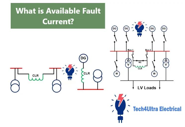
What is Available Fault Current?
Understanding the Core of Electrical Fault Magnitude
Available fault current refers to the maximum electrical current that can flow at a specific point in the system during a short-circuit condition. It’s determined by the impedance of the power source (like a transformer or generator), the conductors, and all components in the path back to the source. The lower the total impedance, the higher the available fault current.
This value is critical in sizing protective devices like circuit breakers and fuses. If the available fault current exceeds what the equipment can handle, it could lead to catastrophic failures. It’s not just a theoretical value—it’s the actual worst-case current your system must safely manage.
To relate this to a real-world scenario: imagine opening a fire hydrant. The amount of water (current) that bursts out depends on the water pressure (voltage) and the pipe size and length (impedance). Similarly, fault current depends on system voltage and impedance, and the available fault current is the full force waiting to erupt during a short circuit.
Read Also: Motor Protection Guide: Types, Devices, Faults & NEC Selection Tips
Why is Available Fault Current Important?
The Role of Fault Calculations in System Safety and Design
Understanding available fault current is not just a technical detail—it’s a matter of safety and compliance. This value directly affects the selection and coordination of protection devices like circuit breakers and fuses. If the protection devices are not rated to handle the available fault current, they may fail to interrupt a fault, leading to arc flashes, equipment damage, or even fires.
For instance, a circuit breaker with a 10 kA interrupt rating would be useless—and dangerous—if installed in a panel where the prospective short-circuit current is 25 kA. That’s why accurate fault current analysis is essential during the design phase.
Both NEC (National Electrical Code) and IEC (International Electrotechnical Commission) standards require that systems be designed to account for the maximum fault current. NEC Article 110.9 specifically mandates that protective devices must interrupt the current without damage. IEC 60909 provides methods for calculating short-circuit currents for compliance.
In short, ignoring the available fault current puts lives and infrastructure at risk. Always match your system’s real-world fault potential with appropriately rated protection equipment.
How to Calculate Available Fault Current (Step-by-Step)
From Transformer Specs to Final Value
Calculating the available fault current at a given point in an electrical system is a crucial part of safe design. Here’s a simplified step-by-step approach:
Step 1: Determine Transformer Specifications
Start by identifying the transformer’s rating (kVA or MVA), the secondary voltage, and its impedance (usually given in %Z on the nameplate).
Step 2: Convert Impedance to a Usable Value
Use the transformer’s impedance percentage to calculate its actual impedance in ohms. This depends on the base voltage and power level.
Step 3: Apply the Standard Formula
Use this formula for three-phase systems:
Available Fault Current (A) = (Transformer kVA × 1,000) / (√3 × Voltage × %Z/100)
Example:
Let’s say you have a 500 kVA, 480 V transformer with 5.5% impedance:
Available Fault Current = (500 × 1,000) / (√3 × 480 × 0.055)
= 500,000 / (1.732 × 480 × 0.055)
= 500,000 / 45.7
≈ 10,938 A
This means the maximum fault current at the transformer’s secondary is approximately 10,938 amps. That’s the prospective short-circuit current your protection equipment must be able to interrupt safely.
Advanced Fault Current Calculation Techniques
When Basic Math Isn’t Enough
Once you go beyond basic transformer-based estimates, more accurate fault current calculations involve using symmetrical components and sequence impedance methods. These techniques are essential when dealing with complex power systems or unbalanced faults, such as line-to-ground or line-to-line events.
In this approach, the system is broken down into positive, negative, and zero-sequence networks. These sequences help analyze unbalanced faults, which can’t be accurately modeled with basic three-phase assumptions. This method is especially important in utility-scale projects or large industrial networks.
To make things easier and more precise, most engineers rely on software tools like ETAP, SKM PowerTools, or EasyPower. These programs automate the process, handling complex network data, equipment specs, and impedance paths to simulate real-world available fault current values at multiple points.
It’s also critical to distinguish between three-phase and single-phase faults. While three-phase faults yield the highest prospective short-circuit current, single-phase faults are more common in practice and often more dangerous due to asymmetric current paths and higher ground fault potential.
If you’re working on a large or critical installation, don’t rely solely on manual calculations—use proven analysis tools and advanced techniques to ensure system safety and code compliance.
Available Fault Current at Different Points
Why It’s Not the Same Everywhere
The available fault current changes depending on where you measure it in the electrical system. At the service entrance, it’s usually the highest because it’s closest to the transformer or utility feed. As current travels through the system, resistance and impedance from conductors and connections reduce the fault current.
In a distribution panel, the fault current is typically lower than at the service entrance due to voltage drops and conductor impedance. By the time it reaches a motor control center (MCC) located far from the source, the prospective short-circuit current may be significantly reduced.
Two key factors affect this drop: distance and conductor type. Longer distances increase resistance, while smaller or higher-resistance conductors (like aluminum vs copper) add impedance to the path.
This variability means you can’t assume the same available fault current across the system. Each panel and equipment point needs its own calculation or verification to ensure protection devices are properly rated and capable of interrupting the expected fault.
Circuit Breakers and Interrupting Capacity
Choosing the Right Protection for Real-World Faults
The available fault current at a panel or equipment location plays a major role in selecting the right circuit breaker. Breakers must have an interrupting rating—also known as an interrupting capacity—that matches or exceeds the prospective short-circuit current at that point.
The interrupting rating is the maximum fault current a breaker can safely interrupt without failing or causing damage. If the available fault current is higher than the breaker’s rating, it could explode or fail to trip—posing major safety risks.
According to the National Electrical Code (NEC) Article 110.9, “Equipment intended to interrupt current at fault levels shall have an interrupting rating not less than the current available at the line terminals of the equipment.” This makes accurate fault current calculations not just good practice—but a legal requirement.
Always match the breaker’s rating with your calculated or tested available fault current to ensure both safety and code compliance. It’s a small detail that prevents very big problems.
Common Mistakes in Fault Current Analysis
Where Things Often Go Wrong
Even experienced engineers can make costly errors when estimating available fault current. One common mistake is overlooking conductor impedance. Long cable runs, especially with small-gauge wires, significantly reduce fault current—ignoring them can result in over-rated breakers or false coordination assumptions.
Another issue is ignoring utility contribution. Many designers assume the utility will always provide fault current data, but often it’s either estimated or not provided at all. Failing to include this in calculations can lead to under-protected systems.
Lastly, misusing default values in software or spreadsheets is a silent trap. Generic values may not reflect real system conditions, which can cause serious gaps in protective device ratings.
Accurate prospective short-circuit current analysis depends on real-world data, correct assumptions, and attention to every part of the circuit—from transformer to terminal.
Watch Also: What Is an Electrical Grid System? Structure, Components, and Advantages Explained
Real-World Examples and Case Studies
When Fault Current Calculations Really Matter
In one industrial facility I worked on, the available fault current at the main service entrance was calculated at over 42,000 amps due to a 1500 kVA transformer and minimal impedance cabling. Using software like ETAP, we confirmed the prospective short-circuit current and selected breakers rated at 50 kA. This ensured compliance with NEC 110.9 and prevented what could have been a dangerous misstep.
In contrast, a residential project showed just how different things can be. A 25 kVA transformer feeding a small panel had a calculated fault current of only 1,050 amps. Here, even a 10 kA-rated breaker was more than adequate. This highlights how system scale and distance from the source affect fault levels drastically.
Unfortunately, I once reviewed a case where a contractor installed 10 kA breakers in a commercial panel that had an available fault current of nearly 22,000 amps. The oversight? Using default software values without utility confirmation or field data. The result was a full panel replacement and a delayed project timeline—not to mention serious risk if a fault had occurred.
These examples reinforce why verifying available fault current is more than theory—it’s a real-world safeguard for both safety and success.
Conclusion
Why Fault Current Knowledge Isn’t Optional
Understanding and accurately calculating available fault current isn’t just a design formality—it’s a cornerstone of electrical safety and system reliability. From transformer specs to breaker ratings, every decision depends on these values. Mistakes can cost time, money, and even lives.
Whether you’re designing an industrial system or reviewing a residential panel, always take the time to verify your fault current assumptions. Your calculations ensure not just code compliance, but the safety of everyone who interacts with the system.
FAQs
Why do we calculate fault current?
We calculate fault current to ensure that protective devices like breakers and fuses can safely interrupt the current without damage or hazard. It’s critical for sizing equipment, coordinating protection, and complying with standards like NEC 110.9 and IEC 60909.
How to label available fault current?
According to NEC 110.24, electrical equipment such as panels and switchboards must be labeled with the maximum available fault current and the date of calculation. The label should be visible and durable, often using engraved or printed plates.
How to calculate PSCC?
To calculate prospective short-circuit current (PSCC), use the formula:
PSCC = Voltage at the point of fault / Total impedance (source + conductors)
Software like SKM or ETAP can help for complex systems, but manual methods work well for basic installations.
How do you calculate battery fault current?
Battery fault current is calculated using:
Fault Current = Battery Voltage / Internal Resistance
Include cable resistance and consider worst-case scenarios. Use manufacturer specs for precise internal resistance values, and always factor in ambient temperature.
Is available fault current the same as fault current?
A: Not exactly. Available fault current refers to the maximum current that could realistically flow during a short circuit, while fault current is a broader term that includes different types and conditions of faults.
?Can I just use default values for fault current
A: That’s risky. Default values may be way off from actual system conditions. Always calculate or verify prospective short-circuit current using real data or software tools.
What happens if I install a breaker with a lower interrupting rating?
A: It may fail catastrophically during a fault. The breaker could explode or catch fire—creating serious hazards. Always match it to your calculated available fault current.
?Does conductor type really affect fault current
A: Yes. Copper vs aluminum, size, and length all affect impedance, which directly impacts fault current values downstream.
How do you measure fault current?
Fault current is usually measured using current transformers (CTs) and protective relays during a test or real fault event. However, it’s more commonly calculated in advance using system parameters and software tools, as measuring actual faults can be risky and destructive.
What is a current fault?
A current fault refers to an abnormal condition where excessive electrical current flows due to a short circuit, ground fault, or equipment failure. This sudden surge can damage components and must be quickly interrupted by protective devices.
What are the two types of fault current?
The two main types of fault current are symmetrical fault current, which is steady and balanced, and asymmetrical fault current, which includes a DC offset and decays over time. Both are critical in determining breaker interrupting ratings and system behavior during a fault.
What is the maximum available fault current label?
This label displays the highest available fault current at a specific equipment location, such as a panel or switchboard. It’s a safety requirement under NEC 110.24 and ensures proper breaker selection and maintenance awareness.
What causes a high fault current?
A high fault current typically results from low system impedance—caused by short cable runs, high-capacity transformers, or strong utility feeds. The closer and more powerful the source, the higher the potential current during a fault.
How to reduce fault current?
To reduce fault current, you can increase system impedance by adding reactors, using longer conductor runs, selecting smaller cable sizes (carefully), or using transformers with higher %Z (impedance). These methods help lower the available fault current at critical points in the system.
How to calculate PFC electrical?
To calculate prospective fault current (PFC), use the formula:
PFC = Voltage / Impedance
For three-phase systems, it becomes:
PFC = (Transformer kVA × 1,000) / (√3 × Voltage × %Z/100)
Use accurate transformer data and conductor impedance for realistic results.
Which fault current is maximum?
The maximum fault current occurs during a three-phase short circuit at the point closest to the power source (typically the service entrance). This condition creates the highest available fault current due to minimal impedance, making it the most critical for equipment sizing.
3 thoughts on “Thermoelectric Generators Explained: How the Seebeck Effect Powers Clean Energy”