Contents
Do you think all parts of an induction motor operate constantly? Here’s a surprising fact: one crucial component only works at startup and then switches off entirely—the centrifugal switch. This article on the Tech4Ultra Electrical website will help you understand the centrifugal switch definition, its vital role in an induction motor, and why even a minor issue with it can lead to complete motor failure. Stick around to uncover how this overlooked part could save you from unexpected repair costs and boost your technical know-how.
Definition and Basic Concept
What is a centrifugal switch?
Let’s keep it simple: a centrifugal switch is a mechanical device used mainly in single-phase induction motors. Its job? To disconnect the starting winding from the circuit once the motor reaches a certain speed—typically around 70–80% of full speed. That’s all it does, but without it, the motor might overheat, become inefficient, or simply fail to start properly.
The centrifugal switch definition revolves around motion and speed. When the motor begins to spin, the rotor’s increasing speed causes weights inside the switch to move outward due to centrifugal force. This movement activates a spring-loaded mechanism that opens the circuit to the start winding, allowing the motor to run on the main winding alone.
Its purpose in electric circuits
In electric motor circuits, the centrifugal switch acts like a smart gatekeeper. During startup, it keeps the start winding connected to provide extra torque. Once the motor hits cruising speed, it disconnects that winding to avoid damage or inefficiency. It’s automatic, mechanical, and highly reliable when functioning correctly.
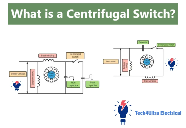
Visual Explanation:
This simple diagram shows the switch mounted on the shaft of the motor, activated by the rotating weights. As speed increases, the weights swing outward and push the switch contacts open, breaking the connection to the start winding.
Read Also: Star Delta Starter: Comprehensive Guide to Working, Circuits, and Applications
Working Principle Explained
Centrifugal force and mechanical movement
To truly understand how a centrifugal switch works, you need to look at the forces at play. When the induction motor starts, it needs a strong push—this is where the start winding comes in. The centrifugal switch is closed at zero speed, keeping this start circuit active.
As the motor shaft begins to rotate, the switch’s internal weights—mounted on the rotor—start spinning. Due to centrifugal force, these weights move outward. This mechanical action pulls on a spring-loaded mechanism that opens the electrical contacts once the desired speed is reached.
Role of switch at various motor speeds
- At standstill (0 RPM): The switch is closed. The start winding is energized to help the motor begin rotation.
- During acceleration: Centrifugal force increases as speed builds up. The weights begin to shift outward.
- At about 70-80% of full speed: The force becomes strong enough to trip the mechanism, opening the switch and disconnecting the start winding.
- At full speed: The motor runs on the main winding only. The centrifugal switch remains open.
Want to visualize it? Check out this animation of centrifugal switch in induction motor:
This animation clearly demonstrates the mechanical motion and timing of how the switch works, from startup to full speed. Watching it makes the concept click instantly—no pun intended!
Centrifugal Switch in Single-Phase Induction Motors
Why it is used specifically in single-phase motors
Here’s the thing—centrifugal switches are practically made for single-phase induction motors. Why? Because single-phase motors can’t start themselves. They lack the rotating magnetic field that three-phase motors generate naturally. That’s where the start winding and the centrifugal switch come in to save the day.
The centrifugal switch in induction motor systems allows the motor to start with the help of a second winding, providing the initial torque needed. Once the motor reaches about 75% of its rated speed, the switch disengages that start winding, letting the motor run normally on its main winding.
How it connects and disconnects the starting winding
The centrifugal switch is wired in series with the start winding. When the motor is off or just starting, the switch contacts are closed—current flows through both windings. As the rotor accelerates and centrifugal force acts on the switch’s weights, the contacts open, breaking the connection to the start winding. It’s like flipping a smart, speed-sensitive switch.
Comparison with other motor types
- Three-phase motors: No centrifugal switch is needed. They produce a self-starting rotating field and have higher starting torque.
- Capacitor-start motors: Also use centrifugal switches, but add a capacitor in series with the start winding for an extra boost.
- Universal motors: Operate on both AC and DC, and don’t require centrifugal switches due to their different internal structure.
So next time you see a single-phase motor, remember—it wouldn’t start at all without that little centrifugal switch doing its silent job behind the scenes.
Watch Also: Bipolar Stepper Motor: Working, Circuit, and Uses
Components of a Centrifugal Switch
Rotor-mounted mechanism
The heart of a centrifugal switch is its rotor-mounted mechanism. This part is directly attached to the motor shaft, meaning it rotates in sync with the motor’s speed. As the rotor spins, a set of weighted arms or flyweights experience outward force—what we call centrifugal force. These weights shift position the faster the shaft turns, triggering the switch operation.
Contacts and spring
Next up are the electrical contacts and the spring. When the motor is stationary, the spring-loaded contacts are closed, completing the circuit to the start winding. As speed builds, the outward motion of the weights pushes on the mechanism, causing the spring to extend and the contacts to open. This breaks the circuit—exactly what’s needed once the motor reaches running speed.
Positioning on motor shaft
Placement matters. The centrifugal switch is usually positioned at the non-drive end of the motor shaft. It’s housed inside the motor casing, tucked near the rear bearing or fan. This spot ensures direct interaction with rotor speed while keeping the switch protected from external elements and vibration.
Altogether, this clever arrangement—rotor mechanism, spring, and contacts—forms a passive yet precise speed-sensitive control system, crucial for starting performance in induction motors.
Advantages and Limitations
Advantages of the centrifugal switch
- Automatic operation: No manual intervention is needed. It engages and disengages the start winding on its own.
- Cost-effective: Simple mechanical design means lower manufacturing and replacement costs.
- Energy-efficient: Disconnecting the start winding after acceleration improves motor efficiency.
- Compact design: The entire switch mechanism fits neatly inside the motor housing.
- Reliability: When maintained, a centrifugal switch can operate effectively for thousands of start cycles.
Limitations of the centrifugal switch
- Wear and tear: Continuous mechanical motion causes eventual degradation of springs and contacts.
- Sensitivity to vibration: External vibrations or imbalanced rotors can trigger false operation or mechanical misalignment.
- Fixed speed threshold: The switch operates at a set speed and cannot be adjusted without redesign.
- Not suitable for all motor types: It’s mainly used in single-phase motors and not ideal for high-speed or precision-controlled motors.
- Replacement complexity: Requires disassembly of the motor to access and replace the switch.
Like any mechanical component, the centrifugal switch comes with both strengths and trade-offs. Knowing these helps in proper application and maintenance planning.
Common Applications
The centrifugal switch may be small, but it plays a big role in many everyday and industrial machines. Here are some of the most common places you’ll find it working quietly behind the scenes:
- HVAC systems: Used in single-phase blower and compressor motors to provide reliable startup performance in heating and cooling systems.
- Washing machines: Helps start the motor that powers the drum, ensuring smooth and powerful rotation from zero speed.
- Pumps: Especially in water and oil pumps, the centrifugal switch ensures that the motor kicks in with enough torque to overcome initial resistance.
- Power tools: Found in large drills, saws, and grinders where strong startup torque is needed for heavy-duty operations.
- Industrial fans: Used to initiate rotation in large ventilation and exhaust fans commonly found in warehouses and factories.
In all these applications, the centrifugal switch in induction motor setups ensures smooth startup, efficiency, and longevity—without requiring user input.
Troubleshooting and Maintenance
Common issues
Like any mechanical component, the centrifugal switch can wear out over time. Some of the most frequent problems include:
- Failure to disconnect: If the switch stays closed, the start winding stays energized, causing overheating and eventual motor damage.
- Burnt contacts: Arcing during switching can burn the electrical contacts, leading to poor conductivity or complete failure.
- Stuck mechanism: Dirt, rust, or broken springs can prevent the weights from moving properly, disrupting normal operation.
How to inspect and test a centrifugal switch
Start with a visual inspection: disconnect power and remove the motor’s rear housing. Look for signs of physical wear, stuck weights, or burnt switch contacts.
Next, use a multimeter to check continuity across the switch terminals. At rest (motor not spinning), the contacts should be closed. Spin the rotor manually—if the contacts don’t open, the switch is faulty.
If needed, replacement involves removing the old switch from the motor shaft and installing a compatible new one. Be sure to re-align it properly to maintain safe switching speed.
Regular inspection of the centrifugal switch in induction motor setups helps prevent motor failures and costly downtime—especially in mission-critical equipment.
Centrifugal Switch vs Potential Relay: A Comparison
Both the centrifugal switch and the potential relay serve the same basic goal—disconnecting the start winding in single-phase motors—but they operate very differently. Here’s how they compare:
| Feature | Centrifugal Switch | Potential Relay |
|---|---|---|
| Operation Mechanism | Mechanical (based on rotor speed) | Electrical (based on voltage rise) |
| Application | Common in split-phase and capacitor-start motors | Used in HVAC compressors and PSC motors |
| Durability | Subject to wear and vibration | No moving parts, longer lifespan |
| Cost | Lower | Higher |
| When to Use | Basic motors needing simple startup | Precision and high-efficiency motor control |
Choose a centrifugal switch for simplicity and low cost. Opt for a potential relay when you need precision and reliability in more demanding systems.
Watch Also: EMF Equation of Transformer Explained: Turns, Voltage, and Formula
Future Alternatives and Trends
The classic centrifugal switch has served well for decades, but newer technologies are beginning to take its place—especially in advanced motor systems.
- Solid-state switching: Replacing mechanical switches with electronic ones reduces wear and improves accuracy. These systems use sensors and transistors to disconnect the start winding at the right moment, silently and reliably.
- Smart motor controllers: Integrated motor control units can manage speed, torque, and switching functions in one compact board. They offer real-time diagnostics, protection features, and smoother performance.
- Reduced use in inverter-driven systems: Variable frequency drives (VFDs) and inverter-based motors eliminate the need for start windings entirely. These motors start gradually using controlled frequencies, making the centrifugal switch obsolete in such setups.
As efficiency and automation become industry standards, the role of the traditional centrifugal switch continues to shrink—though it still holds value in simpler, cost-sensitive applications.
Conclusion
The centrifugal switch may be a small part of an induction motor, but its impact is huge. From enabling smooth startups to protecting motor windings, it’s a critical component that’s often overlooked. Now that you understand the centrifugal switch definition, how it works, and where it’s used, you’re better equipped to troubleshoot, maintain, or even upgrade motor systems effectively. Whether you’re a DIY enthusiast or an engineer, this knowledge helps you make smarter decisions about motor design, repair, and modernization. Don’t underestimate the switch—it’s smarter than it looks!
FAQs
How does a centrifugal switch work?
A centrifugal switch operates using centrifugal force. As the motor shaft spins, internal weights move outward and trigger a spring-loaded mechanism to open the switch contacts. This action disconnects the start winding once the motor reaches about 70–80% of full speed, allowing the motor to run on the main winding only.
What is the symbol of the centrifugal switch?
In electrical diagrams, a centrifugal switch is typically represented by a simple switch symbol with an added label such as “CS” or “Centrifugal SW.” Some diagrams may show it as a normally closed switch that opens with speed.
How to test centrifugal switch using multimeter?
To test a centrifugal switch:
- Disconnect power and access the switch.
- Use a multimeter set to continuity mode.
- Check for continuity across the switch terminals when the motor is off (contacts should be closed).
- Manually rotate the shaft—continuity should break as the mechanism opens the contacts.
If continuity doesn’t change, the switch is likely faulty.
How does a motor switch work?
A motor switch can refer to any device that controls power to a motor. In the case of the centrifugal switch, it works automatically by using the motor’s rotational speed to control when to open or close a circuit, specifically for the start winding. Other motor switches may be manually or electronically operated.
How does a switch work step by step?
A switch operates by controlling the flow of current in a circuit. Here’s a step-by-step breakdown:
- When the switch is closed, it completes the circuit and allows current to flow.
- When the switch is open, it breaks the circuit and stops current flow.
- In the case of a centrifugal switch, it starts in the closed position to allow power to the start winding.
- As the motor gains speed, centrifugal force triggers a mechanical movement.
- This movement causes the switch to open, disconnecting the start winding.
Is a centrifugal switch normally open or closed?
A centrifugal switch is normally closed when the motor is at rest. It stays closed during startup to energize the start winding. Once the motor reaches around 70–80% of full speed, centrifugal force opens the switch, disconnecting the start winding automatically.
How do I know if my centrifugal switch is bad?
Signs of a faulty centrifugal switch include the motor not starting, overheating quickly, or making a humming noise without rotation. You may also hear unusual clicking or rattling sounds from the motor. The most reliable way to confirm is by performing a continuity test with a multimeter and visually inspecting for burnt or stuck contacts.
How to tell if a switch is normally open or closed?
Use a multimeter set to continuity mode. Place the probes across the switch terminals. If the meter beeps or shows continuity without activating the switch, it’s normally closed. If it only shows continuity when triggered (e.g., by pressing or rotating), it’s normally open.
Can a motor work without a centrifugal switch?
A single-phase induction motor will not function properly without a centrifugal switch. It needs the switch to energize and then disconnect the start winding. However, motors using electronic starters or variable frequency drives (VFDs) can eliminate the need for a centrifugal switch entirely.
1 thought on “EMF Equation of Transformer Explained: Turns, Voltage, and Formula”