Contents
Do transformers transfer power with perfect efficiency? That’s a common misconception. In reality, every transformer experiences losses caused by internal factors like transformer impedance, leakage reactance, winding resistance, and transformer resistance. These hidden properties affect voltage regulation, power quality, and overall system performance. In this article on the Tech4Ultra Electrical website, I’ll walk you through what each of these terms really means, why they matter, and how to account for them in real-world applications. Whether you’re troubleshooting a system or just aiming to deepen your technical understanding, this guide will help you make smarter decisions with your power systems.
At its core, transformer impedance is the total opposition a transformer offers to alternating current. It combines both the resistive and reactive components within the transformer windings and core. Simply put, it’s what limits how much current can flow when there’s a voltage difference across the transformer.
Why does this matter? Because impedance affects how voltage drops occur under load, how faults behave, and how efficient power transfer is across the network. A low impedance means higher current during faults—risking damage. A high impedance can cause poor voltage regulation. So yes, transformer impedance plays a major role in system stability and performance.
In the following sections, we’ll dig into what makes up transformer impedance: leakage reactance, transformer resistance, and winding resistance. You’ll learn how each part contributes to real-world behavior, and how to calculate or minimize their impact in your designs or diagnostics.
What Is Resistance in Transformer Windings?
Resistance in transformer windings—often referred to as winding resistance—comes from the very nature of the materials used. Most transformer windings are made of copper or aluminum, both of which have inherent electrical resistance. Even the best conductors resist current flow slightly, and that resistance shows up every time current flows through the windings.
This transformer resistance isn’t just a number on a datasheet—it has real consequences. As current flows, the resistance causes power loss in the form of heat. This is known as I²R loss, where “I” is current and “R” is resistance. The more current, the more heat is generated. And that heat has to go somewhere—usually into the transformer’s oil or surrounding environment.
Why should you care? Because that heat affects transformer efficiency and lifespan. More heat means more cooling is needed and more stress on insulation materials. It also leads to energy losses that reduce system performance over time.
In short, winding resistance is unavoidable but manageable. Engineers reduce it by using larger conductors, high-purity copper, or better winding techniques. Understanding this resistance helps you estimate efficiency, prevent overheating, and design systems that last longer and perform more reliably.
Read Also: EMF Equation of Transformer Explained: Turns, Voltage, and Formula
Understanding Leakage Flux and Leakage Reactance
To understand leakage reactance, you first need to get familiar with leakage flux. In an ideal transformer, all the magnetic flux generated by the primary winding would link perfectly with the secondary winding. But in the real world, that doesn’t happen. Some of the magnetic flux takes a detour—it doesn’t couple with the secondary at all. That detoured magnetic path is what we call leakage flux.
This flux travels through non-magnetic paths—like air, insulation layers, oil, and gaps around the transformer core. It never contributes to the energy transfer between primary and secondary windings. Instead, it forms its own magnetic loop, creating an inductive element that we know as leakage reactance.
So what causes this physically? Several things. The spacing between the windings, the thickness of the insulation, the geometry of the core, and even how tightly the windings are wrapped all impact leakage. Even the dielectric oil around the windings can influence how much flux escapes the core.
This leakage inductance shows up as a kind of magnetic resistance to AC current, and we call it leakage reactance. It increases with frequency and with poor magnetic coupling. While this may sound bad, it’s not always undesirable—sometimes a little leakage reactance helps with voltage regulation or current limiting during faults.
But too much? That’s a problem. High leakage reactance can cause voltage drops, poor dynamic response, and system instability. That’s why transformer designers pay close attention to minimizing unnecessary leakage.
Watch Also: Transformer Efficiency Explained: Calculation, Losses, and Optimization Strategies
The Full Picture: Transformer Impedance
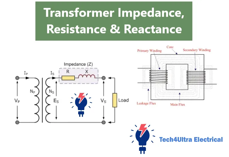
When we talk about transformer impedance, we’re looking at the complete opposition the transformer presents to AC current. It’s not just about how much resistance the copper windings have. It also includes how much the transformer’s magnetic structure “pushes back” through inductive reactance. Put simply, impedance is a combination of two parts: winding resistance and leakage reactance.
The mathematical expression for this looks like:
Z = R + jX
Where:
- Z is the total transformer impedance
- R is the real part, representing transformer resistance
- X is the imaginary part, representing leakage reactance
- j is the imaginary unit (used in electrical engineering to handle phase differences)
Now, here’s something engineers always ask: Is the impedance the same on the primary and secondary sides? Technically, no—but we can refer all values to either side using the square of the turns ratio. That way, we can simplify analysis and calculations without losing accuracy.
Let’s say you’re working with a step-down transformer. If the impedance measured on the high-voltage (primary) side is 5 ohms, and the turns ratio is 10:1, then the referred impedance on the low-voltage (secondary) side would be:
Z_secondary = Z_primary / (turns ratio)² = 5 / 100 = 0.05 ohms
This conversion is vital for fault current analysis, short-circuit studies, and protection coordination. Understanding how transformer impedance behaves across both windings ensures accurate modeling and safer system design.
In essence, impedance is the “fingerprint” of the transformer’s internal behavior—how it handles current, resists faults, and keeps your voltage where it should be.
Watch Also: Impedance Matching Explained: Techniques, Formulas, and Real-World Applications
Voltage Drops and Their Practical Implications
So, what causes voltage drops in a transformer? It all circles back to transformer impedance. When current flows through the transformer, the internal winding resistance and leakage reactance oppose that flow. This opposition causes part of the voltage to be “used up” inside the transformer itself before it ever reaches the load.
This internal consumption of voltage is what we call a voltage drop. It’s not a fault—it’s just basic physics. But the effect can be serious, especially in large power systems or sensitive electronics. The larger the load current, the bigger the drop. And the worse the drop, the more the voltage at the secondary side deviates from the expected value.
This impacts something called voltage regulation. It measures how much the output voltage changes from no-load to full-load conditions. Ideally, we want that change to be as small as possible. But if leakage reactance or winding resistance is high, regulation suffers.
Voltage Equations:
For the primary side:
V₁ = E₁ + I₁R₁ + jI₁X₁
For the secondary side:
V₂ = E₂ – I₂R₂ – jI₂X₂
Where:
- V₁, V₂ are the terminal voltages
- E₁, E₂ are the induced EMFs
- I₁, I₂ are the primary and secondary currents
- R₁, R₂ and X₁, X₂ are the respective resistances and reactances
Understanding these voltage drops helps in selecting the right transformer and ensuring voltage stability across the system. Whether you’re designing a substation or a solar inverter, this knowledge is pure gold.
Impedance in Parallel Transformer Operation
Running transformers in parallel sounds like a simple way to boost capacity, right? But here’s the catch: if their transformer impedance values aren’t closely matched, things can go sideways—fast.
Each transformer’s impedance acts like a “gatekeeper” for how much current it allows to pass through. If one transformer has a slightly lower winding resistance or leakage reactance, it will carry more load than the other—even if both are rated the same. This unequal load sharing leads to overheating, inefficiency, and possibly early failure.
Impedance matching ensures that each transformer shares the load proportionally to its rated capacity. Here’s a simple rule:
Load share ∝ 1 / Z (Impedance)
So, a transformer with lower impedance will “pull” more load, which isn’t ideal unless it’s intentional. That’s why power engineers always double-check impedance percentages before wiring up parallel units. Even a 1–2% mismatch can cause significant imbalance at high loads.
Bottom line: when transformers are operating together, transformer impedance isn’t just a background spec—it’s a dealbreaker. Proper matching keeps your system balanced, efficient, and safe from surprises.
Watch Also: Dead Short in Electrical Circuits: Causes, Detection, and Prevention
Design Considerations to Minimize Magnetic Leakage
One of the biggest design headaches in transformers is minimizing leakage reactance. And it all starts with how the windings are arranged. Ever heard of concentric winding placement? That’s when the primary and secondary windings are wound one over the other, usually on the same limb of the core. This method significantly reduces leakage flux because the magnetic fields from both windings overlap more efficiently.
On the flip side, using separate winding limbs—where the windings are spaced apart—results in more leakage. The greater the physical distance between the windings, the more flux escapes without coupling, which increases leakage reactance. That’s not what you want if you’re aiming for tight voltage regulation and dynamic performance.
Core material matters too. High-permeability materials like silicon steel or amorphous alloys help confine the magnetic flux inside the core and reduce stray flux paths. That’s a big win for efficiency and lower transformer impedance.
So if you’re designing a transformer or troubleshooting issues like poor voltage regulation or unexpected losses, don’t ignore the physical layout. Winding placement and core quality directly affect how your transformer performs under real-world conditions.
Watch Also: Eddy Currents Explained: Theory, Applications, and Real-World Innovations
Testing Transformer Impedance: Methods and Standards
Ever wondered how we actually measure transformer impedance in the lab? It’s not magic—it’s a well-documented process known as the short-circuit test. This method is the go-to standard for determining both leakage reactance and winding resistance.
Here’s how it works: the secondary winding of the transformer is shorted, and a reduced voltage is applied to the primary winding until rated current flows. Because the voltage is low, core losses are negligible, and the only opposition to current flow comes from the impedance. The voltage, current, and power readings taken during this test give you everything you need to calculate resistance (R), reactance (X), and impedance (Z).
The results are typically expressed as a percentage of the rated voltage, known as percent impedance (%Z). It tells you how much voltage drop to expect under full-load conditions. For example, a 5% impedance means the transformer will lose 5% of its voltage when fully loaded.
Engineers also calculate the X/R ratio (reactance to resistance) during this test. Why? Because this ratio is key to understanding how a transformer behaves under fault conditions. A higher X/R ratio means the transformer is more reactive, which affects the peak fault current and relay coordination.
These tests are governed by international standards like IEC 60076 and IEEE C57, ensuring consistency and safety. So if you’re serious about system reliability, accurate impedance testing isn’t optional—it’s essential.
Conclusion
Understanding transformer impedance—and its components like leakage reactance, winding resistance, and transformer resistance—is critical for designing efficient, safe, and reliable power systems. These hidden values affect voltage drops, load sharing, fault currents, and overall performance.
From testing methods to smart design practices, this guide gave you the practical insights to navigate transformer behavior with confidence. Whether you’re troubleshooting or planning a new system, these concepts matter.
Ready to go deeper? Check out our in-depth guides on transformer modeling, short-circuit analysis, and protection coordination for more hands-on applications.
FAQs
Is leakage flux avoidable?
No, leakage flux is not completely avoidable. It’s a natural byproduct of electromagnetic induction in any real-world transformer. However, it can be minimized through smart design choices—like tighter winding placement, using concentric winding methods, and selecting high-permeability core materials. These steps reduce the amount of uncoupled magnetic flux, which helps lower leakage reactance and improves voltage regulation.
Does more impedance mean better performance?
Not necessarily. A higher transformer impedance can help limit fault currents, which might protect downstream equipment. But it also means larger voltage drops under load, reduced efficiency, and poor voltage regulation. The key is balance. Designers aim for an optimal impedance that provides safety without compromising system performance. In parallel transformer operations, mismatched impedance can even lead to load-sharing problems.
Superconductors in transformers?
Yes, superconducting materials have been explored for transformer applications, especially in high-performance and compact designs. Because superconductors have zero winding resistance at cryogenic temperatures, they eliminate I²R losses and dramatically improve efficiency. However, they’re expensive and require complex cooling systems. While promising, widespread adoption of superconducting transformers is still limited by cost and practicality—though they’re definitely worth watching in the future of power systems.
What is the leakage impedance in a transformer?
Leakage impedance in a transformer refers to the combined effect of winding resistance and leakage reactance. It represents how much the transformer opposes current flow due to both electrical resistance and magnetic flux leakage. This value is crucial for determining voltage drops, fault current levels, and proper system coordination.
What is the resistance of a transformer impedance?
The resistance component of transformer impedance is simply the DC resistance of the windings. It causes energy loss in the form of heat (I²R loss) during current flow. Though small in comparison to reactance, it directly affects efficiency and temperature rise within the transformer.
What’s the difference between resistance, reactance, and impedance?
- Resistance (R) opposes current flow and causes energy loss as heat—purely a real value.
- Reactance (X) opposes changes in current, arising from magnetic fields (inductance)—a purely imaginary value.
- Impedance (Z) is the total opposition, combining both R and X using the formula Z = R + jX.
What is meant by leakage reactance of transformer?
Leakage reactance refers to the inductive reactance caused by leakage flux that does not link both the primary and secondary windings. It limits current flow and causes voltage drops under load, impacting performance and voltage regulation. It’s one of the key components of total transformer impedance.
What is the full form of RF transformer?
The full form of RF transformer is Radio Frequency transformer. These are specialized transformers designed to operate at high frequencies, typically from a few kilohertz up to gigahertz. They’re commonly used in communication systems, RF circuits, and impedance matching applications.
How do RF transformers work?
RF transformers function like conventional transformers but are optimized for high-frequency performance. They transfer RF signals from one circuit to another, often while providing impedance matching, voltage step-up or step-down, or isolation. Their design minimizes losses at high frequencies using ferrite cores, transmission line techniques, or air-core windings.
What is the full form of RF in resistance?
In the context of resistance, RF typically does not refer to resistance directly. Instead, it still stands for Radio Frequency. When used with resistance, such as “RF resistance,” it usually means the resistance observed in components when operating at radio frequencies—where factors like skin effect and parasitic reactance become significant.
What is the full form of RF?
RF stands for Radio Frequency. It refers to the electromagnetic wave frequencies in the range of about 3 kHz to 300 GHz. RF is widely used in wireless communications, radar, broadcasting, and signal processing.
What is RF impedance?
RF impedance is the complex impedance a circuit or component presents to an RF signal. It includes both resistance and reactance and is usually expressed in ohms (Ω). Common values like 50Ω and 75Ω are used in RF systems for proper matching to avoid signal reflection and power loss.
What is the difference between IR and RF?
IR (Infrared) and RF (Radio Frequency) are both types of electromagnetic signals used in wireless communication. The key differences:
- IR operates at higher frequencies (infrared light), requires line-of-sight, and is often used in remote controls.
- RF works over longer distances, doesn’t require direct line-of-sight, and is used in radio, Wi-Fi, and cellular networks.
Each has its own applications depending on the range, power, and environmental constraints.
1 thought on “Eddy Currents Explained: Theory, Applications, and Real-World Innovations”