Contents
Do you think all electricity meters work the same way? That’s a common misconception. In reality, there are different types of meters, each designed with unique mechanisms and purposes. Among the most important are the induction type meter, electromechanical energy meter, and watt-hour meter. In this article on the Tech4Ultra Electrical website, you’ll gain a clear and practical understanding of how these devices work, why they matter, and how they directly impact your electricity bills. If you’ve ever wondered what’s really behind that spinning disc or blinking light on your meter, you’re about to find out.
Brief Overview of Energy Meters
Energy meters are essential devices used to measure the amount of electrical energy consumed by a residence, business, or an electrically powered device. These meters are the backbone of billing systems in electric utilities, translating the invisible flow of electricity into quantifiable units. Over the years, energy meters have evolved from mechanical designs to digital models, yet one of the most iconic and historically significant types remains the electromechanical energy meter.
Importance of Electromechanical Induction Meters in Power Measurement
The induction type meter—a common form of watt-hour meter—has long been relied upon for its durability and accuracy in measuring alternating current (AC) electrical energy. It operates based on electromagnetic induction and is designed to calculate the power usage over time. These meters were widely adopted due to their simplicity, affordability, and resilience in varied environmental conditions. Even with the rise of smart meters, they remain a benchmark in power measurement technology.
Read Also: Centrifugal Switch in Induction Motors: Working, Applications, and Troubleshooting Guide
What Is an Induction Type Energy Meter?
Definition
An induction type meter is a mechanical device used to measure the electrical energy consumed in kilowatt-hours (kWh). It is specifically designed for use in alternating current (AC) systems and is one of the most widely used types of watt-hour meter in residential and commercial settings.
Explanation of Electromechanical Watt-Hour Meters
Also known as an electromechanical energy meter, this type of meter works on the principle of electromagnetic induction. Inside the device, coils create magnetic fields that interact with a rotating aluminum disc. The speed of the disc’s rotation is directly proportional to the power consumed, and this movement drives a mechanical counter to record the total energy usage. These meters are valued for their simplicity, long lifespan, and consistent performance in standard energy monitoring applications.
Construction of an Induction Type Energy Meter
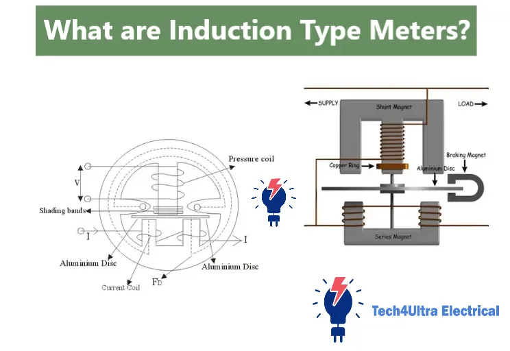
Current Coil and Voltage Coil
The induction type meter relies on two main coils: the current coil and the voltage coil. The current coil is connected in series with the load and carries the line current, while the voltage coil is connected in parallel and carries a current proportional to the line voltage. These coils are strategically placed to produce magnetic fields that interact with each other to induce a torque on the rotating disc.
Non-Magnetic Aluminum Disc
At the heart of the electromechanical energy meter is a lightweight, non-magnetic aluminum disc. This disc is mounted on a spindle and positioned between the magnetic fields generated by the two coils. As these fields interact, they induce eddy currents in the disc, which in turn produce a force that causes it to rotate. The speed of rotation is proportional to the power consumed, making the disc a critical component in a watt-hour meter.
Permanent Magnet and Braking System
To ensure the aluminum disc does not spin uncontrollably, a permanent magnet is installed near its edge. This magnet produces a braking force that opposes the motion of the disc through electromagnetic damping. The braking system is calibrated to maintain accuracy in the energy measurement by controlling the disc’s speed relative to the load.
Enclosure and Mechanical Components
The internal components of the induction type meter are housed in a durable, tamper-resistant enclosure, often made of metal or high-grade plastic. The enclosure protects the delicate internal mechanisms from dust, moisture, and tampering. Additional mechanical parts include gears, bearings, and a register unit that displays the total energy consumed in kilowatt-hours. This display is often a mechanical counter that increments as the disc rotates, offering a reliable readout of energy usage.
Working Principle: How Induction Energy Meters Measure Energy
Application of Electromagnetic Induction
The induction type meter operates based on the principle of electromagnetic induction, a concept introduced by Faraday. When alternating current flows through the current coil and voltage coil, each generates a magnetic field that alternates with the frequency of the power supply. These magnetic fields intersect in the space where the aluminum disc is located, and it’s this interaction that initiates the energy measurement process.
Role of Eddy Currents
As the alternating magnetic fields pass through the non-magnetic aluminum disc, they induce circulating currents called eddy currents. These currents are localized loops of electrical current that flow within the disc itself. The interaction between the eddy currents and the magnetic fields produces a torque. This torque is what causes the disc to start rotating, and it is directly proportional to the product of the voltage and the current — in other words, the real power being consumed.
Interaction of Magnetic Fields
The voltage coil is typically designed to produce a magnetic flux that lags the applied voltage by 90 degrees due to the inclusion of a highly inductive coil. Meanwhile, the current coil produces a flux in phase with the line current. The time phase difference between these two fields creates the rotating magnetic effect that is key to the meter’s operation. The strength of this interaction determines the torque applied to the disc.
Disc Rotation and Energy Measurement
As the disc rotates, it drives a mechanical counter through a system of gears. This counter is calibrated to display the total electrical energy consumption in kilowatt-hours (kWh). The faster the energy usage, the quicker the disc spins. The permanent magnet provides braking torque to ensure accuracy. This simple but precise mechanism allows the watt-hour meter to reliably track energy over long periods.
Watch Also: Casing Capping Wiring: Types and Installation Guide
Torque and Its Role in Measurement
Driving Torque Generation
In an induction type meter, the driving torque is what sets the measurement process in motion. This torque is generated when the alternating magnetic fields from the current and voltage coils interact within the aluminum disc. As these fields cut through the disc, they induce eddy currents that interact with the magnetic fields, creating a force. This force causes the disc to rotate, and the strength of the driving torque is directly proportional to the power consumed — more power means more torque, and therefore faster disc rotation.
Braking Torque and the Role of Permanent Magnet
To prevent the disc from spinning uncontrollably, a braking torque is applied using a permanent magnet. Positioned strategically near the edge of the rotating disc, this magnet creates its own magnetic field. As the disc moves through this field, it induces additional eddy currents that oppose its motion. This creates a damping effect, which slows down the rotation as needed and ensures the meter doesn’t over-record energy usage.
Balancing Torques for Accuracy
For the electromechanical energy meter to function accurately, the driving torque and the braking torque must be perfectly balanced. When the two torques are equal, the disc reaches a steady speed that reflects the actual power being consumed. This equilibrium ensures precise readings on the watt-hour meter and maintains consistent long-term performance.
Lag Adjustment Devices and Calibration Methods
Need for Phase Shift Correction
In an induction type meter, accuracy depends on maintaining the correct phase relationship between the voltage coil flux and the applied voltage. Ideally, the flux produced by the voltage coil should lag the voltage by exactly 90 degrees. However, due to core losses and inductive effects, this phase shift often deviates. Without correction, this can cause the meter to register incorrect energy values, particularly at low power factors.
How Lag Devices Fine-Tune Readings
To correct these deviations, lag adjustment devices are used. These are typically copper shading bands or loops fitted on the central limb of the voltage coil core. By adjusting the position of these bands, technicians can control the phase angle of the voltage coil’s magnetic field. This fine-tuning ensures that the induced flux aligns more accurately with the expected phase difference, improving the performance of the electromechanical energy meter.
Practical Calibration Techniques
Calibration of a watt-hour meter involves comparing its reading with a known standard load. Technicians apply a specific voltage and current, observe the disc’s rotation speed, and adjust the lag device or braking magnet as needed. This process ensures precise alignment with the true energy consumption values.
Watch Also: Measurement of Resistance: A Complete Guide
Types of Induction Energy Meters
Single-Phase Meters
The most common type of induction type meter used in homes is the single-phase meter. Designed for residential or small commercial settings, this meter measures energy consumption in single-phase AC circuits. It contains one current coil and one voltage coil that work together to rotate the aluminum disc based on the load. These meters are compact, cost-effective, and ideal for tracking lower power consumption accurately.
Poly-Phase Meters
For industrial or large commercial applications, electromechanical energy meters are available in poly-phase configurations, such as three-phase meters. These meters are built to handle multiple phases of electrical input and generally include two or more measuring elements within the same housing. They can record total power consumption across all phases and are essential for environments where energy loads are unbalanced or high.
Differences and Applications
While both types operate using the same electromagnetic principles, their internal construction and application vary. Single-phase watt-hour meters are used where power needs are modest, whereas poly-phase meters are essential for factories, malls, and office buildings where power distribution is complex and loads are heavier.
Advantages and Disadvantages
Benefits: Durability, Low Cost, Reliability
One of the main reasons the induction type meter has been widely used for decades is its durability. These meters are built to last for many years with minimal maintenance. They are also cost-effective, making them a budget-friendly option for utility companies and consumers alike. Thanks to their mechanical simplicity, they offer high reliability in standard operating conditions, especially in residential and small commercial applications.
Another major benefit of the electromechanical energy meter is that it doesn’t require external power to operate. This makes it useful in remote areas where power infrastructure may be limited. Their ability to provide accurate readings over long periods, even in harsh environments, has made them a standard tool in energy billing systems worldwide.
Limitations: Friction Losses, Wear, Magnetic Interference
Despite their advantages, watt-hour meters of this type come with several limitations. Mechanical parts like the disc and bearings are subject to friction, which can reduce measurement accuracy over time. Wear and tear also mean that regular calibration may be needed. Additionally, these meters can be affected by strong external magnetic fields, which may interfere with their operation and potentially lead to tampering or errors in readings.
Modern Alternatives and Evolution
Transition to Electronic and Smart Meters
As technology has advanced, the classic induction type meter is gradually being replaced by electronic and smart meters. These modern devices offer enhanced functionality, including real-time data tracking, remote reading, and better integration with digital infrastructure. Smart meters eliminate moving parts, reducing maintenance and increasing accuracy over time. They also allow consumers and utilities to monitor energy consumption more closely and manage load distribution efficiently.
Comparison with Digital Energy Meters
Unlike electromechanical energy meters, digital meters use microcontrollers and sensors to measure electrical parameters. While both types aim to calculate energy usage in kilowatt-hours, digital meters provide faster response times, easier installation, and better data visualization. Although watt-hour meters based on induction are still in use, especially in older installations, the global shift is clearly moving toward digital technology due to its versatility, long-term cost savings, and smart grid compatibility.
Practical Applications in Power Systems
Residential and Industrial Use
The induction type meter has played a foundational role in both residential and industrial energy management. In homes, it is commonly used to monitor electricity usage for billing purposes, offering reliable and long-lasting service. In industrial settings, especially where single-phase loads are common, these meters have served as dependable tools for tracking energy consumption over extended periods.
Relevance in Metering and Billing
As a classic form of the watt-hour meter, the electromechanical energy meter has helped utilities implement standardized metering and billing practices. It provides straightforward readings in kilowatt-hours, making it easy for both consumers and energy providers to understand and manage usage. Even with the rise of smart metering, many older systems still rely on induction meters due to their simplicity, resistance to tampering, and low operational cost — proving they remain relevant in various parts of the world today.
Watch Also: What is a Megger? Working Principle and Applications
Common Errors and Maintenance Tips
Sources of Error: Temperature, Mechanical Wear, Calibration Drift
Like any mechanical device, the induction type meter is not immune to operational errors. One common issue is temperature variation; extreme heat or cold can affect the performance of internal components, especially the aluminum disc and magnetic coils. These components function in ways similar to those in an induction motor, where thermal and magnetic changes impact performance. Mechanical wear is another factor — over time, friction in the bearings can slow disc rotation, leading to under-recording of energy. Calibration drift may also occur as the magnetic fields weaken or components age, causing inaccurate readings from the electromechanical energy meter.
Maintenance Best Practices
To ensure accuracy, regular inspection and preventive maintenance are key. This includes checking for dust buildup, lubricating moving parts, and inspecting the braking magnet for signs of demagnetization. Periodic calibration using a reference load can correct any drift and realign readings with actual usage. Additionally, sealing the meter properly and protecting it from tampering or external magnetic interference helps maintain the integrity of the watt-hour meter over its operational life.
Conclusion
The induction type meter has stood the test of time as a dependable tool for measuring electrical energy. Despite the rise of digital and smart technologies, these electromechanical energy meters continue to play a vital role in power systems around the world. Their durability, simplicity, and cost-efficiency make them especially valuable in regions where infrastructure upgrades are still ongoing. As a classic watt-hour meter, the induction meter remains a key component in the history and evolution of energy metering and management.
FAQs
What is an induction meter?
An induction type meter is a mechanical device used to measure the consumption of electrical energy in alternating current (AC) systems. It works by using the principle of electromagnetic induction to rotate a disc, with the speed of rotation directly related to the power consumed.
What is the theory of induction type meters?
The working theory behind induction type meters is based on electromagnetic induction. When current flows through the voltage and current coils, alternating magnetic fields are produced. These fields induce eddy currents in an aluminum disc, causing it to rotate. The number of rotations corresponds to the energy used.
What is the induction type?
“Induction type” refers to a category of meters or devices that use electromagnetic induction to function. In energy metering, it specifically refers to electromechanical energy meters that calculate power usage by the movement of a disc influenced by magnetic fields.
Where are the induction type energy meters used?
Watt-hour meters of the induction type are commonly used in residential, commercial, and some light industrial settings. They are typically installed by utility companies to monitor electricity usage for billing and consumption tracking, especially in older or less digitally connected areas.