Contents
Did you know that a single undetected generator fault can cost thousands of dollars in damages within seconds? Many assume that once a generator is running, everything’s fine—but that’s far from the truth. Without proper protection schemes, even a minor stator fault can spiral into a major shutdown. In this article on the Tech4Ultra Electrical website, I’ll walk you through the critical aspects of generator protection, how to implement effective stator fault protection, and the most reliable protection schemes to keep your systems safe, efficient, and uninterrupted.
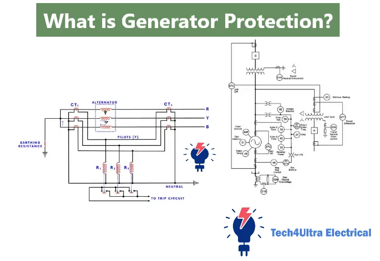
What is Generator Protection?
Back when I first started working with power systems, I underestimated just how critical generator protection really was. I figured as long as the machine spun and the lights stayed on, everything was fine. Big mistake. Generator protection is all about safeguarding the generator from internal and external faults—short circuits, overloads, overvoltages—you name it. The objective? Simple: prevent damage, minimize downtime, and avoid expensive repairs or total failure.
Importance for Grid Stability and Asset Longevity
Think of a generator as the heart of a power station. If it fails, the whole grid can feel the shock. And I’ve seen it firsthand—one stator fault that wasn’t caught in time led to a cascading shutdown across several substations. That’s why implementing proper protection schemes isn’t just a luxury—it’s a necessity for both grid stability and asset longevity. Good protection systems extend the generator’s life and keep its performance within safe limits, even under stress.
Link to IEEE/IEC Standards
If you’re serious about designing or auditing generator protection systems, you can’t ignore the IEEE and IEC standards. IEEE C37.102 and IEC 60034-1, for example, lay out the backbone for safe, reliable protection design. These standards don’t just offer guidelines—they’re battle-tested frameworks that reduce guesswork and help ensure compliance and consistency across installations.
Read Also: Differential Protection of Generators: Complete Guide
Core Protection Principles and Relay Functions
Types of Generator Faults
If you’ve ever dealt with a generator trip during peak load, you know the pain. Generator faults come in many flavors, and each one demands a tailored protection response. Common types include:
- Stator faults: These include phase-to-phase, phase-to-ground, and turn-to-turn faults. They’re often catastrophic if not detected quickly.
- Rotor faults: Ground faults in the rotor winding can lead to field failure and reduced stability.
- Overvoltage and overcurrent conditions: Can arise from load rejection or excitation issues.
- Loss of excitation: Leads to instability and severe voltage fluctuations.
ANSI/IEEE Code Mapping
Protection functions are typically identified using ANSI/IEEE standard device numbers. This makes it easier to reference and configure protection schemes across different systems. Here’s a quick mapping table:
| Device Code | Function |
|---|---|
| 87G | Stator fault protection (Differential) |
| 40 | Loss of excitation |
| 50/51 | Instantaneous and time-overcurrent protection |
| 59 | Overvoltage protection |
| 64R | Rotor earth fault protection |
Overview of Protective Relay Types
There’s no one-size-fits-all when it comes to relays. From electromechanical to microprocessor-based, each has its place. In older plants, you’ll still find classic induction-type relays, but modern facilities rely on digital relays. These smart devices offer better accuracy, self-diagnostics, and even remote configuration.
Ultimately, choosing the right relay isn’t just about cost—it’s about response time, compatibility, and how well it integrates with the rest of your generator protection strategy.
Stator Protection Techniques
Differential Protection (87G)
Back when I was troubleshooting a nuisance trip on a generator, I learned firsthand the power of 87G protection. Stator fault protection using differential relays is one of the most effective methods. The concept is simple: measure the current entering and leaving the stator windings. Any significant mismatch? That’s a red flag for internal faults. This method reacts quickly—often within milliseconds—and isolates the faulted generator section before it escalates. It’s not foolproof, though; it needs precise CT matching and calibration to avoid false trips.
Ground Fault Protection
Stator ground faults are a nightmare if left unchecked. These faults can cause localized insulation burnouts and total generator failure. Common protection methods include zero-sequence voltage detection and low-impedance neutral grounding. Some plants also use a 59N relay to detect unbalanced voltages. The trick is sensitivity—catching high-resistance faults early before they evolve into something more destructive.
Third Harmonic and Subharmonic Methods
Want to get fancy? Here’s where harmonic detection steps in. Stator fault protection using third harmonic voltage monitoring is clever: under normal conditions, the third harmonic component is predictable and localized near the neutral point. A shift or reduction signals a potential ground fault. Subharmonic injection, on the other hand, uses a low-frequency signal to test insulation integrity continuously—very useful during startup and standby. These methods are non-intrusive and work great as secondary protection layers.
Monitoring Insulation Resistance
This is your long-game strategy. Instead of waiting for a stator fault to happen, monitor the insulation resistance of the windings over time. Tools like insulation monitoring devices or offline megger testing can give you a heads-up on degrading insulation. It’s preventative, cost-effective, and can literally save a generator from catastrophic failure if you act on early warnings.
Watch Also: Electrical Switchgear Protection Explained
Rotor Protection Strategies
Rotor Ground Fault and Brush Lift-Off
Here’s something I learned the hard way—rotor faults can sneak up on you. Once, during a routine maintenance check, we discovered brush lift-off damage that had gone unnoticed for weeks. It started with minor wear but escalated into insulation breakdown. Generator protection must include monitoring for rotor ground faults and mechanical issues like brush lift-off. These aren’t just maintenance concerns—they can cause unbalanced magnetic fields, which lead to vibration and efficiency losses.
Rotor Earth Fault Detection
Unlike stator faults, rotor earth faults are trickier because the rotor circuit is isolated and often floating. To detect faults, we usually apply a low-voltage DC or AC signal between the rotor and ground. A drop in insulation resistance indicates a leakage path. Many systems use a 64F relay or a simple bridge circuit for continuous monitoring. It’s especially important during high-load conditions when the insulation is under maximum stress.
AC Injection Techniques
One advanced method I’ve used is AC injection. A small alternating signal is superimposed on the rotor winding, and the return signal is analyzed for phase shifts or resistance changes. This method is sensitive enough to detect partial discharges and insulation deterioration long before a full-blown fault occurs. It’s excellent for online condition monitoring in critical units.
Vibration and Temperature-Based Diagnostics
When your rotor starts shaking or overheating, take it seriously. Vibration sensors and thermal monitoring systems are your first line of defense. Excessive vibration often points to imbalances or misalignment, while rising temperatures can signal overload, bearing issues, or insulation fatigue. These diagnostics work best when integrated into SCADA systems for real-time alerts and trend analysis, making your protection schemes smarter and more predictive.
Loss of Field & Overexcitation Protection
Mho Characteristics and Capability Curves
One of the first times I encountered a generator trip due to loss of field, I had no idea how critical the protection zone setup was. That’s when I got introduced to Mho characteristics and capability curves. The Mho relay (ANSI 40) operates based on the generator’s impedance, and it uses a circular characteristic on the R-X diagram to detect when excitation drops dangerously low. Essentially, if your operating point drifts into that zone, you’ve got a generator protection trigger. The capability curve of the generator also defines how far you can push it before risking damage due to instability or overheating. Cross those boundaries, and you’re in unsafe territory.
V/Hz Protection Mechanisms
Now let’s talk about something less obvious: V/Hz protection (ANSI 24). This comes into play during events like load rejection, where voltage can spike while frequency drops. That ratio—volts per hertz—becomes a killer. Exceeding safe V/Hz limits can saturate the generator core and lead to insulation failure. Protection relays constantly monitor this ratio and trip if it breaches predefined thresholds. I once saw a delay of just a few seconds fry a transformer winding downstream. Trust me, this isn’t a setting you want to get wrong.
Real-Time Field Current Monitoring
Last but not least, keep an eye on that field current. Real-time monitoring allows operators to detect trends that precede failures—like gradual loss of excitation or impending rotor faults. Most digital protection schemes now include live telemetry from the excitation system. It’s not just about alarms; it’s about knowing when to act before damage becomes irreversible. And believe me, you want that warning before your phone rings in the middle of the night.
Protection Coordination with System Stability
Out-of-Step and Anti-Motoring Schemes
I’ll never forget the day our plant tripped due to an undetected out-of-step condition. It looked like everything was running fine, but the generator had already lost synchronism. That’s where out-of-step protection (ANSI 78) steps in. It monitors impedance swings and detects when the generator slips poles—an early sign of instability. On the flip side, anti-motoring schemes (ANSI 32R) prevent a generator from acting as a motor if its prime mover fails. Without it, the generator draws power from the grid, overheating and risking severe mechanical damage. A well-tuned generator protection system must include both.
Grid Codes and Synchronization Loss Handling
Grid operators don’t mess around when it comes to synchronization. Most grid codes require automatic disconnection in the event of sync loss, usually detected through voltage angle and frequency differences. Loss-of-synchronism relays compare the generator’s terminal voltage phase angle with the grid reference. If they drift apart too far or too fast, you risk system oscillations or blackouts. That’s why it’s critical for your protection schemes to align with national and regional grid codes like ENTSO-E in Europe or NERC in North America. Non-compliance isn’t just a technical issue—it’s a regulatory one.
Protective Zone Overlaps
Good coordination means zero blind spots. That’s why we overlap protective zones between generator, transformer, and busbar protections. Each zone—backed by differential, distance, or overcurrent relays—must detect faults within its scope but also tolerate minor transients. A failure to coordinate can lead to misoperation or even a blackout. And believe me, when you’re explaining to management why a 5-minute fault knocked out an entire section of the grid, you’ll wish you had double-checked those settings.
Advanced Digital and IoT-Based Protection
Role of Digital Relays (IEDs)
The first time I replaced an old electromechanical relay with a digital IED, I wasn’t convinced it would make a huge difference. But wow—digital relays changed the game. Intelligent Electronic Devices (IEDs) are now the heart of modern generator protection. They combine multiple protection functions—differential, overcurrent, ground fault, and even logic control—into one compact unit. What’s more, they provide better precision, self-checks, event recording, and time synchronization. This makes fault analysis not only easier but actionable. Plus, firmware updates mean your relay can evolve without hardware swaps. Try doing that with a legacy device!
Remote Monitoring and Analytics
If your system can’t talk to you, you’re already behind. With the rise of IoT, protection schemes are no longer limited to on-site control rooms. Today, remote monitoring platforms allow you to view relay status, download disturbance records, and track insulation resistance from anywhere. Once, I spotted a rise in stator temperature through a remote dashboard while I was 300 miles away. We took preventive action, and it saved the rotor windings. Data analytics tools now help trend minor anomalies and forecast potential issues. It’s not just about alerts—it’s about insight.
AI-Based Anomaly Detection
Now let’s talk about the future—AI isn’t coming; it’s already here. AI-powered platforms use machine learning to detect patterns that traditional relays would miss. Think about it: what if your system could learn the difference between a nuisance trip and a real fault based on historical data? These platforms continuously analyze waveforms, vibration data, and temperature profiles to spot anomalies early. Combined with IoT sensors, this makes stator fault protection and other advanced schemes not just reactive, but predictive. That’s a level of reliability no analog system could ever dream of achieving.
Testing, Maintenance and Compliance
Routine Relay Testing Checklist
In my early days, I once assumed that if a relay hadn’t tripped in years, it was working fine. That’s not how it works. Regular testing is non-negotiable. A standard relay testing checklist should include:
- Verification of pickup/dropout settings
- Secondary injection to confirm response curves
- Trip circuit continuity and battery health checks
- Testing of time delays and logic functions
- Calibration verification for digital IEDs
Neglecting these checks? That’s how you end up with a protection scheme that fails you when you need it most.
Protection Failure Analysis
Every failed trip or false alarm tells a story. Failure analysis helps uncover root causes—whether it’s a CT polarity issue, a firmware bug, or just human error in the settings. I always document these incidents meticulously and update relay settings or maintenance protocols accordingly. This builds institutional knowledge and prevents repeat failures.
ISO/IEEE Compliance Protocols
Standards aren’t just red tape—they’re lifelines. Following protocols like IEEE C37, IEC 60255, and ISO 9001 ensures your generator protection system isn’t just functional but also verifiable. Auditors love documentation, and so will you when you need to prove that you did everything right. Proper labeling, time-stamped logs, and test reports can mean the difference between a regulatory fine and a clean audit.
Watch Also: Motor Protection Guide: Types, Devices, Faults & NEC Selection Tips
Real-World Case Studies
North-East Blackout Revisit
Let’s rewind to the infamous North-East blackout of 2003. One of the key contributors? Inadequate generator protection coordination. Several generators failed to disconnect during an out-of-step condition, leading to wide-area instability. Protection systems didn’t react quickly enough, and relays failed to isolate faulted segments. The result: over 50 million people without power. It’s a textbook example of why robust protection schemes, effective power system protection, and out-of-step detection (ANSI 78) are essential—not just locally, but across regional grids.
Industrial Case on Differential Miscoordination
At an industrial plant I consulted for, a differential relay (87G) kept tripping during normal load increases. At first, the team suspected a CT issue, but after digging into the settings, we discovered that mismatched tap ratios were the culprit. The protection system misinterpreted normal inrush as a fault. It was a classic case of poor relay coordination. Once corrected, the stator fault protection worked flawlessly. This scenario taught the team two key lessons: always verify CT configurations during maintenance, and never underestimate the complexity of inrush current behavior in large alternators—a crucial part of power system protection strategy.
Both cases underline one truth—protection isn’t just about hardware or settings. It’s about understanding the system’s behavior and planning for both the expected and the worst-case scenarios.
Conclusion & Best Practices
Protection Planning Guide
If there’s one thing I’ve learned over the years, it’s that generator protection is never a “set it and forget it” job. Effective protection starts with a solid plan—define fault scenarios, identify critical equipment, and select the right protection schemes for each risk. Make sure relay settings reflect both your operational profile and worst-case conditions. Involve both protection engineers and operations staff in the planning process. It’s not just technical—it’s strategic.
Integration into Asset Management
Protection systems should be fully embedded in your asset management program. Link relay data and fault history to maintenance schedules. Use analytics to identify wear patterns or component degradation before it becomes critical. A proactive approach turns protection from a reactive safety net into a predictive decision tool.
Summary of Key Takeaways
- Stator fault protection and rotor monitoring are essential for long-term generator health.
- Coordination with grid stability systems ensures wider operational resilience.
- Digital relays and AI tools enhance fault detection and predictive diagnostics.
- Routine testing and standards compliance are critical for reliability and audits.
Bottom line? Treat your protection system like a living part of your operation—test it, trust it, and always keep improving it.
FAQs
What are the common types of generator faults in PDF?
Common types of generator faults include stator winding faults (phase-to-phase or phase-to-ground), rotor earth faults, loss of excitation, overcurrent, and overvoltage events. Many technical guides and standards like IEEE C37.102 provide detailed fault classification and protection responses. These are often summarized in PDF manuals for protection engineers.
What is generator safety?
Generator safety refers to the practices and systems in place to ensure that a generator operates without posing risks to people, equipment, or the power grid. This includes electrical protection via relays, mechanical safety systems, thermal monitoring, and adherence to standards like IEC 60034 and OSHA guidelines. Proper generator protection is a key component of generator safety.
What is generator differential protection?
Generator differential protection (ANSI 87G) is a scheme designed to detect internal faults by comparing the current entering and exiting the stator windings. Any significant mismatch indicates a fault, prompting an immediate trip to isolate the generator. It’s one of the most precise and reliable forms of stator fault protection.
What are generator faults?
Generator faults are abnormal conditions that disrupt normal operation. These include electrical issues like short circuits in the stator or rotor, mechanical faults like bearing failure, and environmental problems like overheating or moisture ingress. Each fault type requires specific protection schemes to mitigate damage and avoid system downtime.
4 thoughts on “Motor Protection Guide: Types, Devices, Faults & NEC Selection Tips”